
Method and a device for measuring axial polarizing angle of polarizer

a technology of polarizer and axial polarizing angle, which is applied in the direction of polarization-affecting properties, optical radiation measurement, instruments, etc., can solve the problems of long measurement time and unsuitable for real-time audit, and achieve the effect of reducing the time required for measuring

Inactive Publication Date: 2008-06-05
OPTIMAX TECHNOLOGY CORPORATION
View PDF7 Cites 0 Cited by
  • Summary
  • Abstract
  • Description
  • Claims
  • Application Information

AI Technical Summary

Benefits of technology

[0010]One objective of the present invention is to provide an apparatus and a method for measuring an axial polarizing angle of a polarizer without rotating the optical components, and the signals are quickly collected to achieve the effect of reducing the time required for measuring.
[0011]Another objective of the present invention is to provide an apparatus and a method for measuring an axial polarizing angle of a polarizer, which is adaptable for measuring a large number of polarizers of various specifications for lowering the measurement cost and reducing the occurrence of erroneousness.
[0012]Still another objective of the present invention is to provide an apparatus and a method for measuring an axial polarizing angle of a polarizer to lower the time required for measuring to less than 0.1 second, and to be used in the real-time audit production process.
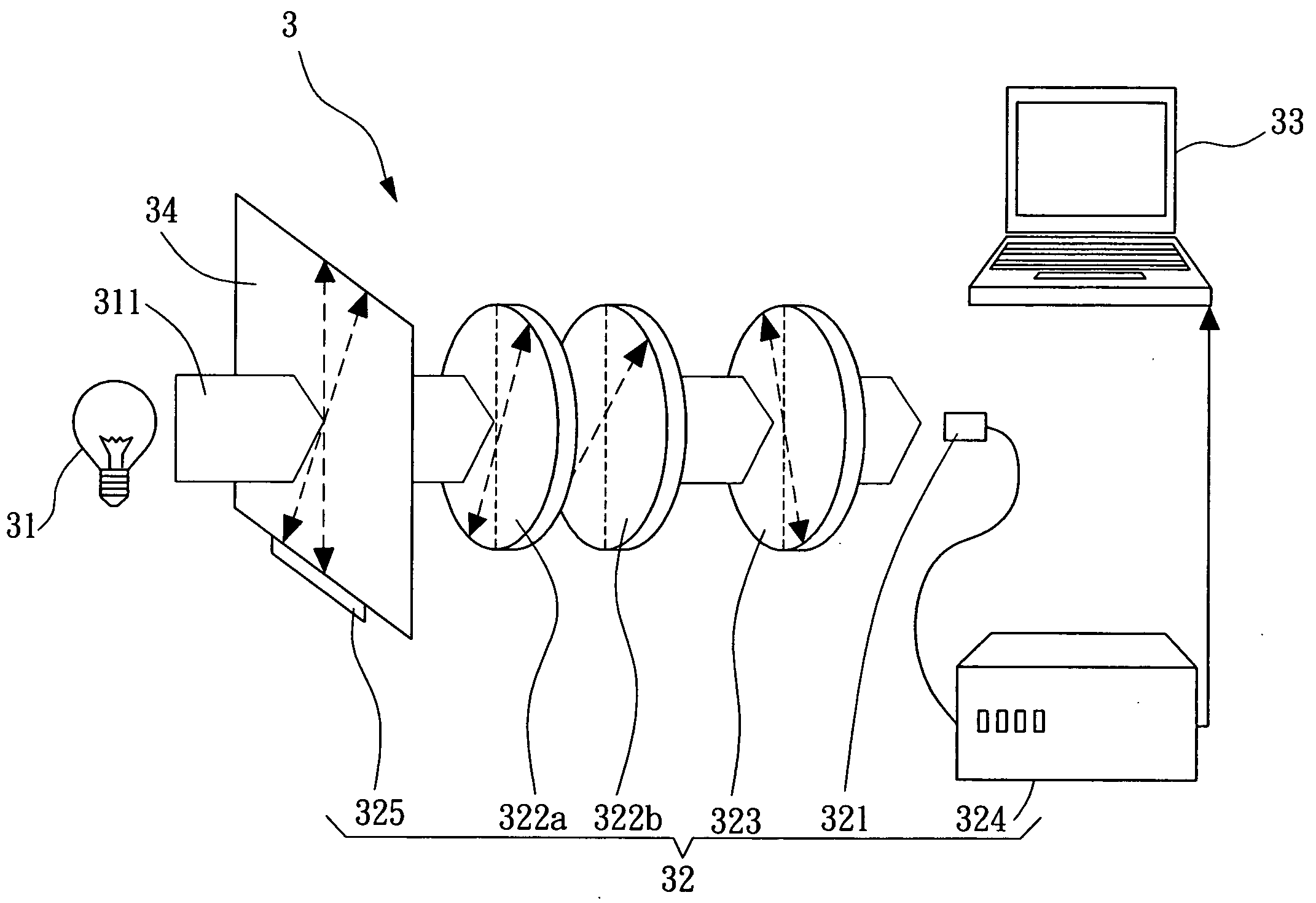
[0013]In order to achieve aforementioned objectives, an embodiment of the apparatus for measuring an axial polarizing angle of a polarizer in accordance with the present invention is disclosed. The apparatus can have a to-be-measured polarizer disposed therein, and comprises a light generating device, a light polarizing device and a measurement comparison device. The light generating device provides a light source. The light polarizing device is disposed corresponding to the light generating device to load the to-be-measured polarizer, and measures a light signal after the light source passes through the to-be-measured polarizer without rotating the to-be-measured polarizer, and transforms it into readable data. The measurement comparison device is electrically connected with the light polarizing device and has at least one preset comparison data to receive the data provided by the light polarizing device and compare it with the comparison data. Thus, after comparing the data provided by the light polarizing device with the comparison data, an axial polarizing angle of the to-be-measured polarizer is quickly and accurately measured and calculated.

Problems solved by technology

The above-mentioned conventional apparatus 2 for measuring an axial polarizing angle of the polarizer needs to rotate some of its components and it takes a long time to perform the measurement (usually one or several seconds), thus is not suitable for the real-time audit.
Therefore, solution to the abovementioned problem is the most urgent issue for the industry right now.

Method used


Image

  • Method and a device for measuring axial polarizing angle of polarizer
  • Method and a device for measuring axial polarizing angle of polarizer
  • Method and a device for measuring axial polarizing angle of polarizer

Examples


Embodiment Construction

[0038]Please refer to FIG. 3A, which is a schematic drawing showing the apparatus for measuring an axial polarizing angle of the polarizer in a preferred embodiment of the present invention. The apparatus 3 for measuring an axial polarizing angle of the polarizer includes a light generating device 31, a light polarizing device 32 and a measurement comparison device 33. The light generating device 31 provides a light source 311, and the light source 311 may be provided at several different wavelengths (i.e. polychrome light or white light). The light polarizing device 32 is disposed corresponding to the light generating device 31 for receiving the light signal of the light source 311 and transforming it into readable data. In the preferred embodiment of the present invention, the light polarizing device 32 further includes a light collecting module 321, at least one retardation plate 322a, 322b, a preset polarizer 323 (the axial polarizing angle is known) and a light signal transform...


PUM


Abstract

The present invention relates to a device and a method for measuring an axial polarizing angle of a polarizer. The apparatus can have a to-be-measured polarizer disposed therein, and comprises a light generating device, a light polarizing device and a measurement comparison device. The light generating device provides a light source. The light polarizing device is disposed corresponding to the light generating device to load the to-be-measured polarizer, and measures a light signal after the light source passes through the to-be-measured polarizer without rotating the to-be-measured polarizer, and transforms it into readable data. The measurement comparison device is electrically connected with the light polarizing device and has at least one preset comparison data to receive the data provided by the light polarizing device and compare it with the comparison data. Thus, after comparing the data provided by the light polarizing device with the comparison data, an axial polarizing angle of the to-be-measured polarizer is quickly and accurately measured and calculated.

Description

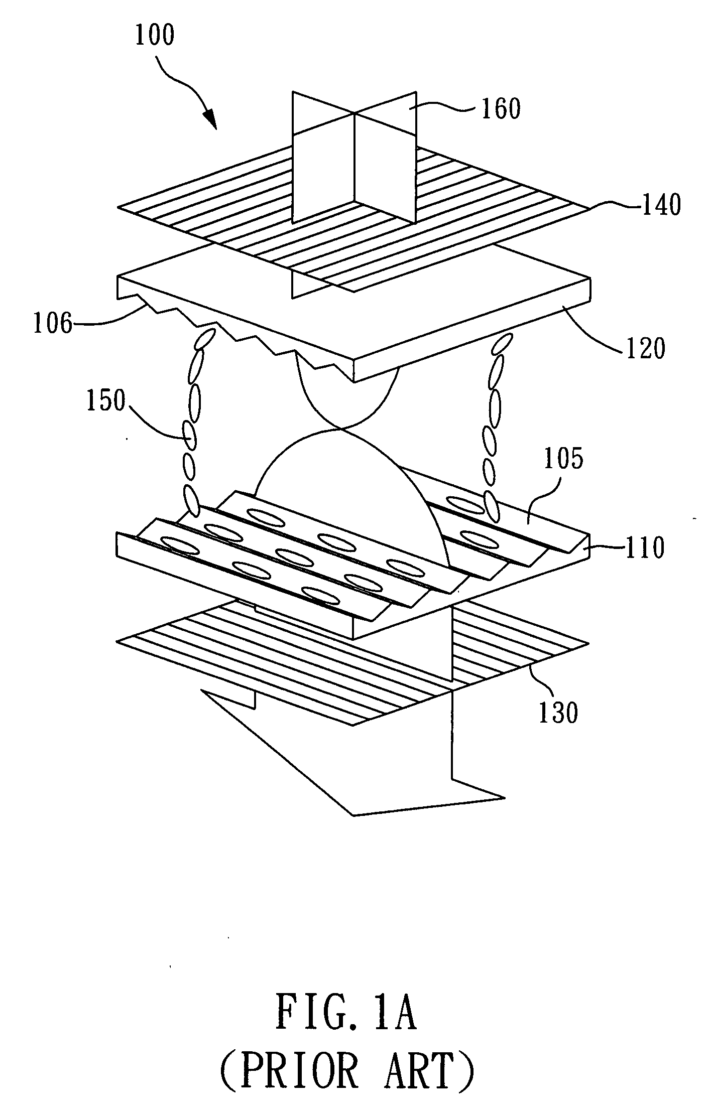
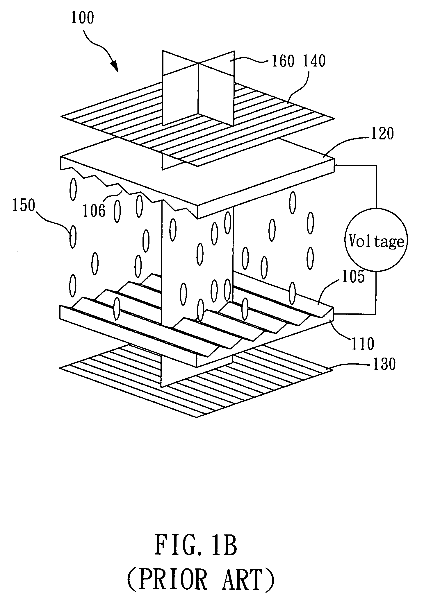
BACKGROUND OF INVENTION[0001]1. Field of the Invention[0002]The present invention relates to an apparatus and a method for measuring an axial polarizing angle of a polarizer, and more particularly, to an apparatus and a method that quickly measures an axial polarizing angle of the polarizer without rotating the polarizer, so as to achieve real-time audit of a manufacturing process of the polarizer.[0003]2. Description of the Prior Art[0004]LCD has been widely used in various electronic information devices, such as televisions, computers, cell phones and PDA. For LCD panels on the market, liquid crystal molecules are between solid phase and liquid phase, and such molecules not only flows easily as liquid does in response to external forces, but also have the property of optical anisotropy as a crystal does. Therefore, an external electric field can drive the arrangement of liquid crystal to other directions, resulting in the change of the optical characteristics of lights passing thr...

Claims


Application Information

Patent Timeline
IPC IPC(8): G01J4/00
CPCG01N2021/8477G01N21/21
Inventor LIN, JIA CHIANGCHANG, CHING SENLIN, CHING HUANGWU, LONG HAI
Owner OPTIMAX TECHNOLOGY CORPORATION
Learn More