Multilayer ceramic capacitor

a ceramic capacitor and multi-layer technology, applied in the direction of fixed capacitors, stacked capacitors, fixed capacitor details, etc., can solve the problems of difficult to achieve both a high dielectric constant, and the degree of design freedom is limited, so as to suppress the force that causes the substrate, suppress the distortion in the low-activity region, and suppress the effect of “squeal”

Active Publication Date: 2008-06-05
MURATA MFG CO LTD
View PDF11 Cites 22 Cited by
  • Summary
  • Abstract
  • Description
  • Claims
  • Application Information

AI Technical Summary

Benefits of technology

[0027]According to the present invention, the low-activity regions are positioned in the respective cylindrical regions in the active part, each cylindrical region having a radius of 0.025L about a line in which a plane parallel to the end surfaces and passing through a position of an end edge of one of the external electrodes on the first main surface of the capacitor body intersects the surface of the active part adjacent to the first main surface. To put it briefly, in the active part, the low-activity regions are positioned near the respective end edges of the respective external electrodes. Additionally, the facing area of the internal electrodes in the low-activity regions is less than or equal to one fifth that of the internal electrodes in a normal region having the same volume as that of the low-activity regions. Therefore, distortion in the low-activity regions that occurs when an electric field is applied to the multilayer ceramic capacitor can be made small. This makes it possible to suppress force that causes the substrate on which the multilayer ceramic capacitor is mounted to bend and thereby to suppress “squeal”.
[0028]Also, since the low-activity regions where the facing area of the internal electrodes is made relatively small for suppressing “squeal” according to the present invention are limited regions in the active part, such as regions near the end edges of the external electrodes, it is possible to suppress the “squeal” without significantly sacrificing the capacitances that can be obtained.
[0029]Additionally, when the active part according to the present invention is symmetric with respect to a plane parallel to the first and second main surfaces and passing through a center between the first and second main surfaces, there is no need to make a distinction between the first and second main surfaces when the multilayer ceramic capacitor is to be mounted. This makes it possible to achieve an efficient mounting process and reduce mistakes in mounting.

Problems solved by technology

When the level of “squeal” increases, a noise problem arises.
However, there are problems using the technique in which a distortion is suppressed by an improvement in material composition as described in Patent Document 1, in that it is difficult to achieve both a high dielectric constant and the like, and suppression of a distortion, and that the degree of design freedom is limited.
However, the method of suppressing “squeal” described in Patent Document 2 has a problem in that the process of forming a metal film while maintaining a proper insulating gap is complicated.

Method used


Image

  • Multilayer ceramic capacitor
  • Multilayer ceramic capacitor
  • Multilayer ceramic capacitor

Examples


first embodiment

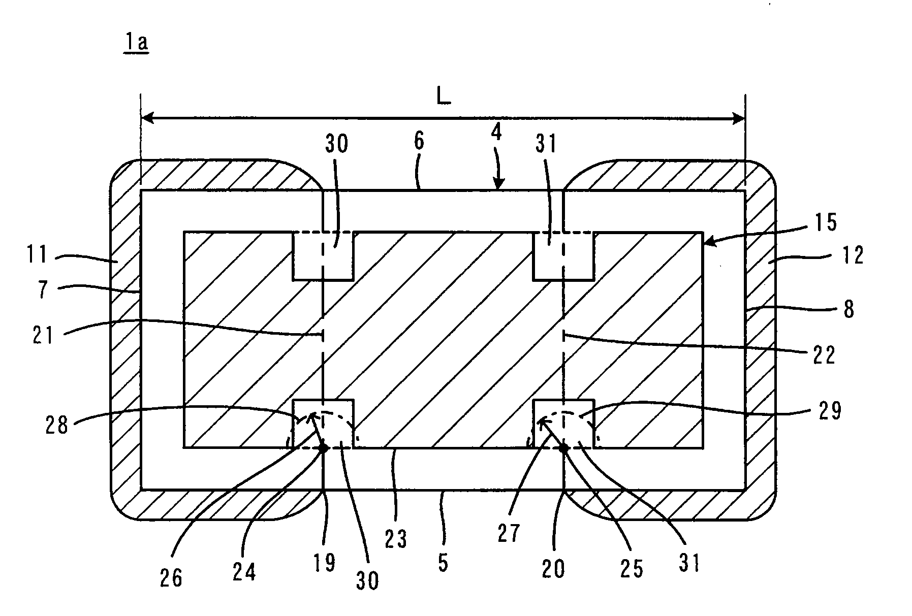
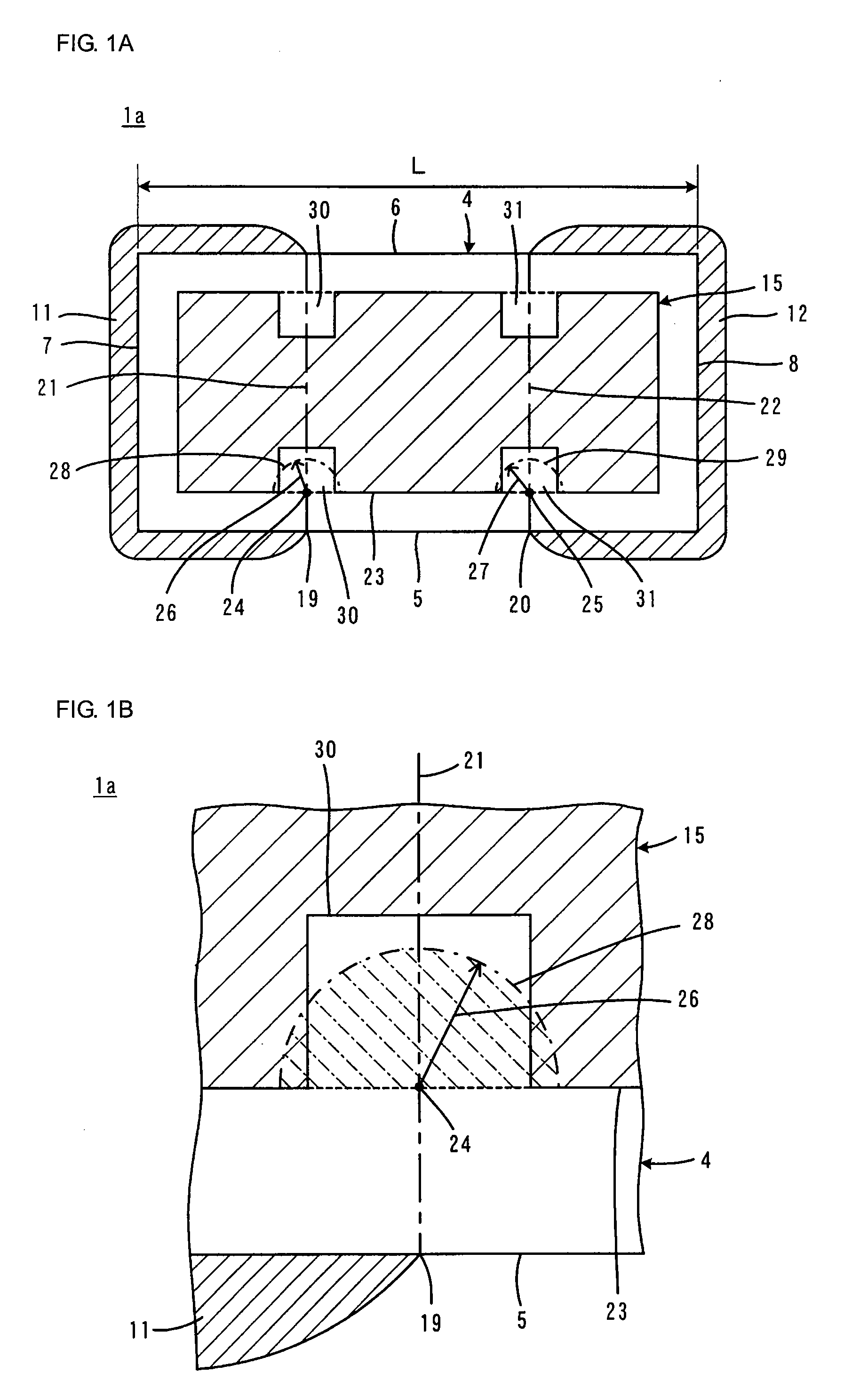
[0068]FIGS. 1A, 1B, 2A and 2B illustrate the present invention. As in the case of FIG. 15, FIG. 1A shows the active part 15 instead of internal electrodes. A multilayer ceramic capacitor 1a illustrated in FIG. 1A is to be mounted on a substrate with its lower side being adjacent to the substrate. FIG. 1B is an enlarged view of part of FIG. 1A. FIG. 2A and FIG. 2B are plan views illustrating an internal electrode pattern in the multilayer ceramic capacitor 1a of FIG. 1A. In FIGS. 1A and 1B and FIGS. 2A and 2B, elements equivalent to those illustrated in FIG. 14 and FIG. 15 are given the same reference numerals and redundant description is omitted. Although not illustrated in FIG. 14, first and second side surfaces 9 and 10 are illustrated in FIG. 2.

[0069]A characteristic configuration of the multilayer ceramic capacitor 1a according to the first embodiment will now be described.

[0070]Reference character L denotes the distance between the first and second end surfaces 7 and 8 in the l...

second embodiment

[0077]FIGS. 3A and 3B illustrate a multilayer ceramic capacitor 1b according to the present invention. FIG. 3 corresponds to FIG. 2 and shows an exemplary modification of the internal electrode pattern. In FIG. 3, elements equivalent to those illustrated in FIG. 2 are given the same reference numerals and redundant description is omitted.

[0078]As illustrated in FIG. 3A, the notches 32 and 33 formed in the internal electrode 3a have openings on different sides of the internal electrode 3a. Likewise, as illustrated in FIG. 3B, the notches 34 and 35 formed in the internal electrode 3b have openings on different sides of the internal electrode 3b.

[0079]The internal electrode patterns illustrated in both FIG. 2 and FIG. 3 are formed such that the internal electrodes 3a and 3b do not face each other in the low-activity regions 30 and 31, that is, such that the facing area of the internal electrodes 3a and 3b in the low-activity regions 30 and 31 is zero. However, this facing area does no...

third embodiment

[0081]FIG. 4 illustrate a multilayer ceramic capacitor 1c according to the present invention. FIG. 4 corresponds to FIG. 2 and shows another exemplary modification of the internal electrode pattern. In FIG. 4, elements equivalent to those illustrated in FIG. 2 are given the same reference numerals and redundant description is omitted.

[0082]As illustrated in FIG. 4A, notches 36 and 37 for providing the low-activity region 31 are formed in the internal electrode 3a with their openings oriented in directions opposite each other. A narrow portion 38 is left between the notches 36 and 37. Likewise, as illustrated in FIG. 4B, notches 39 and 40 for providing the low-activity region 30 are formed in the internal electrode 3b with their openings oriented in directions opposite each other. A narrow portion 41 is left between the notches 39 and 40. The width of both the narrow portions 41 and 38 is less than or equal to one fifth that of the other portions of the internal electrodes 3a and 3b....


PUM

PropertyMeasurementUnit
dielectric constantaaaaaaaaaa
thicknessaaaaaaaaaa
thicknessaaaaaaaaaa

Abstract

The “squeal” that occurs when an electric field is applied to a multilayer ceramic capacitor mounted on a substrate is suppressed by providing in an active part contributing to formation of capacitances between internal electrodes facing each other in a capacitor body, low-activity regions positioned near respective end edges of respective external electrodes. A facing area of the internal electrodes in the low-activity regions is less than or equal to one fifth that of the internal electrodes in a normal region having the same volume as that of the low-activity regions. This makes it possible to suppress occurrence of electric-field-induced distortion near the external electrodes bonded to a substrate and reduce the force that causes the substrate to bend.

Description

[0001]This is a continuation of application Serial No. PCT / JP2006 / 313725, filed Jul. 11, 2006.TECHNICAL FIELD[0002]The present invention relates to a multilayer ceramic capacitor and particularly to improvements for suppressing a “squeal” which occurs when an electric field is applied to a multilayer ceramic capacitor mounted on a substrate.BACKGROUND ART[0003]FIG. 14 is a cross-sectional view of a mounted multilayer ceramic capacitor 1.[0004]The multilayer ceramic capacitor 1 includes a capacitor body 4 having a multilayer structure including a plurality of dielectric ceramic layers 2 and a plurality of internal electrodes 3a and 3b formed along a plurality of respective interfaces between the dielectric ceramic layers 2. The capacitor body 4 has a rectangular parallelepiped shape defined by first and second main surfaces 5 and 6 extending in a direction in which the dielectric ceramic layers 2 extend, first and second end surfaces 7 and 8 extending in a direction orthogonal to the...

Claims


Application Information

Patent Timeline
Patent Type & Authority Applications(United States)
IPC IPC(8): H01G4/005
CPCH01G4/012H01G4/30H01G4/232H01G4/12
Inventor NAKANO, MAKITOINOUE, NORIYUKIKAWASAKI, KENICHI
Owner MURATA MFG CO LTD
Why Eureka
Try Eureka