Tool for chip removing machining and a basic body therefor

a technology of chip removal and tooling, which is applied in the direction of cutting inserts, manufacturing tools, shaping cutters, etc., can solve the problems of inefficient and almost provisional cooling of previously known turning tools of the kind in question, and the difficulty of efficient cooling of cutting inserts

Inactive Publication Date: 2008-06-05
SANDVIK INTELLECTUAL PROPERTY AB
View PDF6 Cites 34 Cited by
  • Summary
  • Abstract
  • Description
  • Claims
  • Application Information

AI Technical Summary

Benefits of technology

[0009]The idea behind the invention is to lead in a liquid or fluid, in particular high-pressure liquid, into the pivotably movable tightening part of the tool via a channel section that is entirely or partly housed in a bridge, which like the joint is formed of the proper material in the basic body, and which crosses or bridges one of the two gaps, more precisely in a locus spaced apart from the axis of the joint around which the tightening part is pivotable. By providing a channel inside the tightening part and connecting the same with a traditional channel in the fixing part via a bridge that is at least somewhat thicker or stu

Problems solved by technology

As a consequence of, on one hand, the fact that the front portions of the support and tightening parts have to be slender, and on the other hand, the fact that the movable tightening part exclusively is connected to the rest of the basic body via a thin, elastically resilient material portion serving as a joint for the tightening part, difficulties arise in cooling the cutting insert in an efficient way.
Thus, the cooling of previously known turning tools of the kind in question has been effected in an inefficient and almost provisional way, more precisely by means of two pipe condui

Method used


Image

  • Tool for chip removing machining and a basic body therefor
  • Tool for chip removing machining and a basic body therefor
  • Tool for chip removing machining and a basic body therefor

Examples


Embodiment Construction

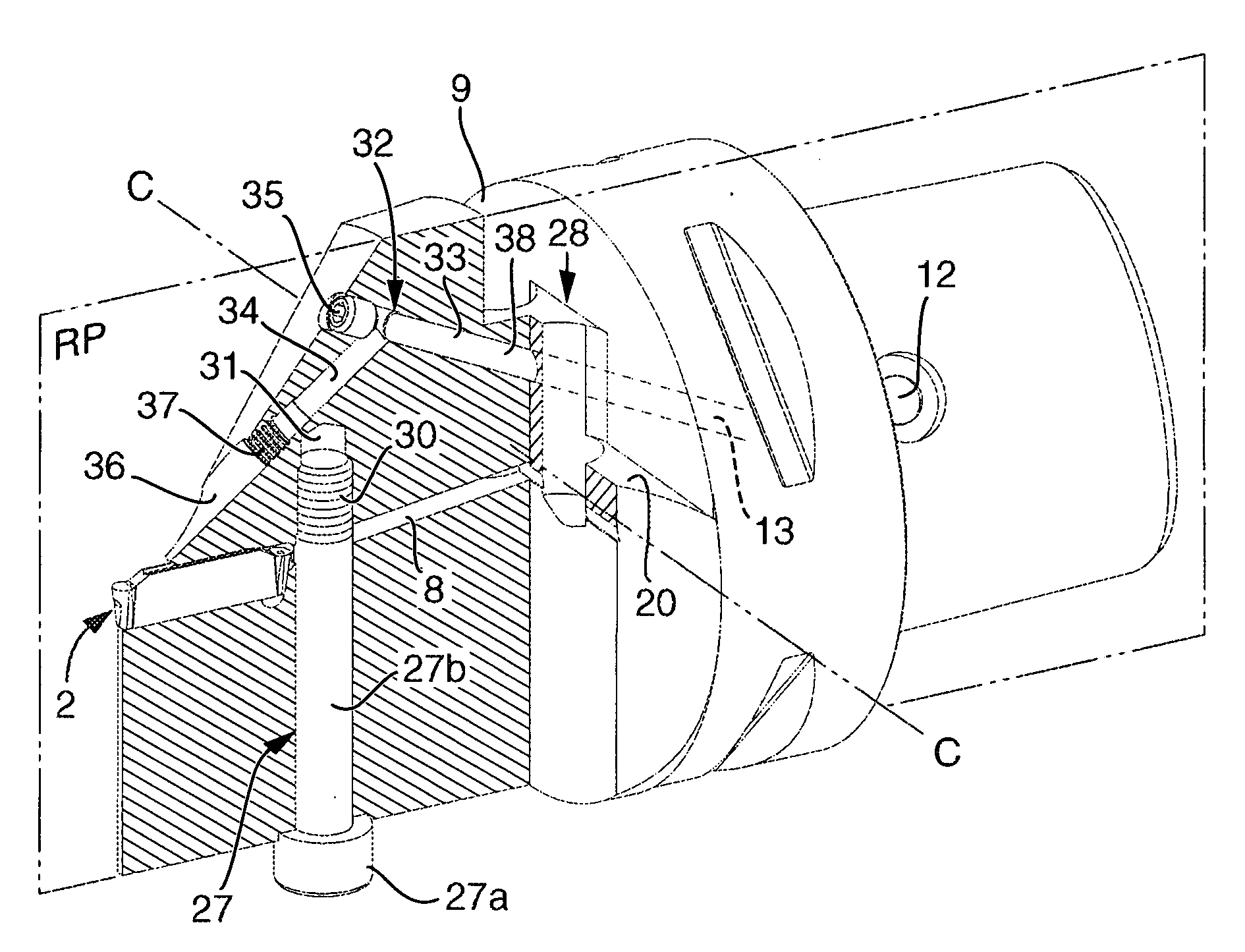
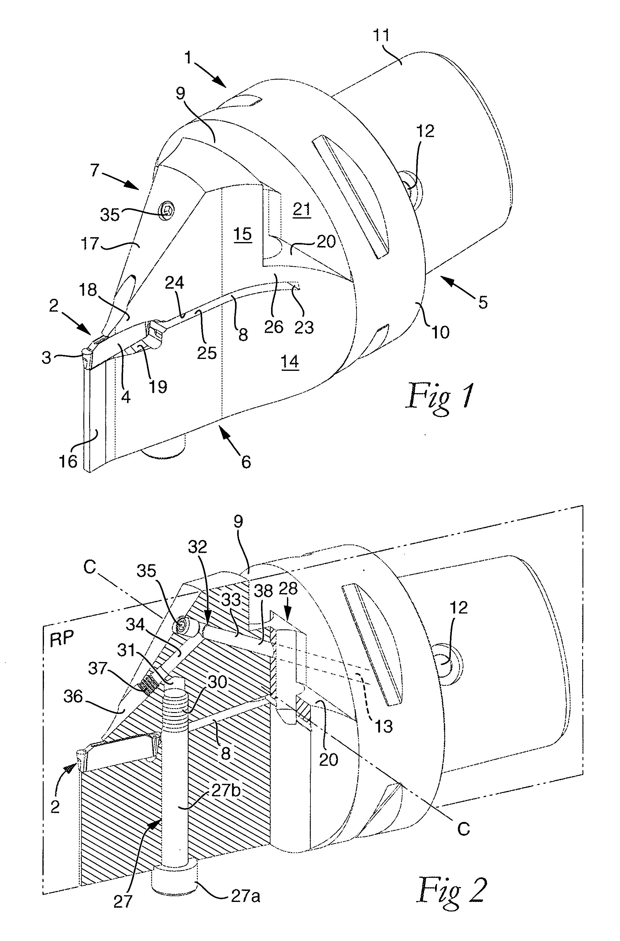
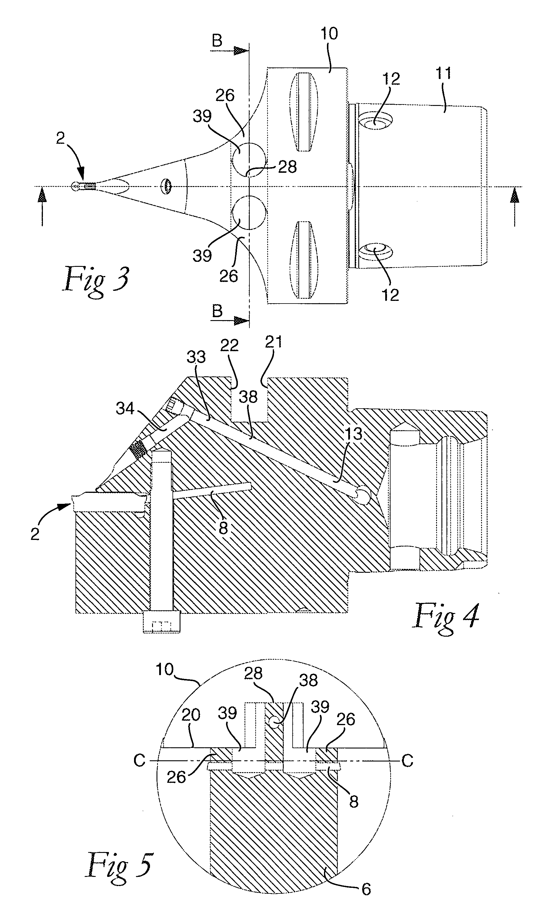
[0019]The turning tool shown in FIGS. 1-5, which in practice can be used for parting, grooving and profile turning, includes two main components, viz. a basic body in its entirety designated 1, and a replaceable cutting insert 2. In this case, the cutting insert 2 has an elongate basic shape and is indexable in two positions by including a pair of opposite, circular cutting edges 3, which are formed on round material portions having a downwardly tapering shape. The flat intermediate portion 4 of the cutting insert, which extends between the two opposite ends, has a thickness that is smaller than the diameter of the cutting edges 3.

[0020]Suitably, the cutting insert 2 is manufactured from cemented carbide or another hard and wear-resistant material, while the basic body 1 is manufactured from steel or an equivalent material of the type that has at least a certain inherent elasticity.

[0021]The basic body 1 includes a rear fixing part 5, a front supporting part 6, and a tightening part...


PUM

PropertyMeasurementUnit
Pressureaaaaaaaaaa
Angleaaaaaaaaaa
Resilienceaaaaaaaaaa

Abstract

A tool for chip removing machining, including a replaceable cutting insert and a basic body. The basic body includes a rear fixing part, a front supporting part having an insert seat, and a tightening part situated over the support part, and spaced-apart from the front supporting part by a first gap and from the rear fixing part by a second gap. The tightening part is connected to the basic body via a joint. The joint is formed of at least one elastically resilient material portion and has an axis around which the tightening part is pivoted in order to press the cutting insert against the insert seat by a front finger. The rear fixing part includes an internal channel for feed of a fluid in the forward direction through the basic body. The internal channel extends into a second channel inside the tightening part via a channel section that is entirely or partly housed in a bridge which, like the joint, is formed of the material in the basic body, and which bridges one of the first and second gaps.

Description

[0001]This application claims priority under 35 U.S.C. § 119 to Sweden Patent Application No. 0602557-7, filed on Nov. 28, 2006, the disclosure of which is incorporated by reference herein in its entirety.FIELD OF THE INVENTION[0002]The present invention relates generally to a tool for chip removing machining of the type that includes a replaceable cutting insert and a basic body. The basic body includes a rear fixing part, a front supporting part having an insert seat in which the cutting insert is placed, and a tightening part situated over the support part and spaced-apart from the two other parts via two gaps. The tightening part is connected to the rest of the basic body via a joint made in the form of at least one elastically resilient material portion and having an axis around which the tightening part is pivotable in order to, by a front finger, be able to press the cutting insert against the insert seat. The fixing part includes an internal channel for feed of a fluid in th...

Claims


Application Information

Patent Timeline
IPC IPC(8): B23B29/00
CPCB23B27/04B23B27/06B23B27/10B23B29/043Y10T407/14B23B2250/12B23B2260/124Y10T407/2288Y10T407/25B23B2205/02B23B27/22B23B29/14B23B27/086
Inventor SJOO, STURE
Owner SANDVIK INTELLECTUAL PROPERTY AB
Why Eureka
Try Eureka