Device and method for protecting gate terminal and lead

a technology of gate terminals and lead, applied in the direction of basic electric elements, electrical equipment, semiconductor devices, etc., can solve problems such as failure of display panels, and achieve the effect of not increasing the tft fabrication cycle tim

Inactive Publication Date: 2005-02-17
INTELLECTUAL VENTURES FUND 82
View PDF5 Cites 3 Cited by
  • Summary
  • Abstract
  • Description
  • Claims
  • Application Information

AI Technical Summary

Benefits of technology

[0010] It is still another object of this invention that formation of the resist region can be combined to the present TFT fabrication process without increasing TFT fabrication cycle time.
[0011] In one embodiment, a device for protecting a gate terminal and lead at stage of scribing and spalling a LCD panel is provided, wherein the LCD panel comprises a first substrate with thin film transistor array thereon and a second substrate thereon within color filter opposite to the thin film transistor array. The device comprises a resist region covering the gate terminal and lead of the gate electrode line and between a passivation layer and a gate insulating layer, and located at a scribing line on margin of the second substrate of the panel, thereby the resist region can protect the passivation layer, and the gate insulating layer from cracking, the gate terminal and lead from corrosion after a portion of the second substrate is removed along the scribing line.
[0012] A method for protecting a gate terminal and lead at stage of scribing and spalling a LCD panel is also provided. The method compris

Problems solved by technology

This will cause the

Method used


Image

  • Device and method for protecting gate terminal and lead
  • Device and method for protecting gate terminal and lead
  • Device and method for protecting gate terminal and lead

Examples


Embodiment Construction

[0020] Some sample embodiments of the present invention will now be described in greater detail. Nevertheless, it should be recognized that the present invention can be practiced in a wide range of other embodiments besides those explicitly described, and the scope of the present invention is expressly not limited except as specified in the accompanying claims.

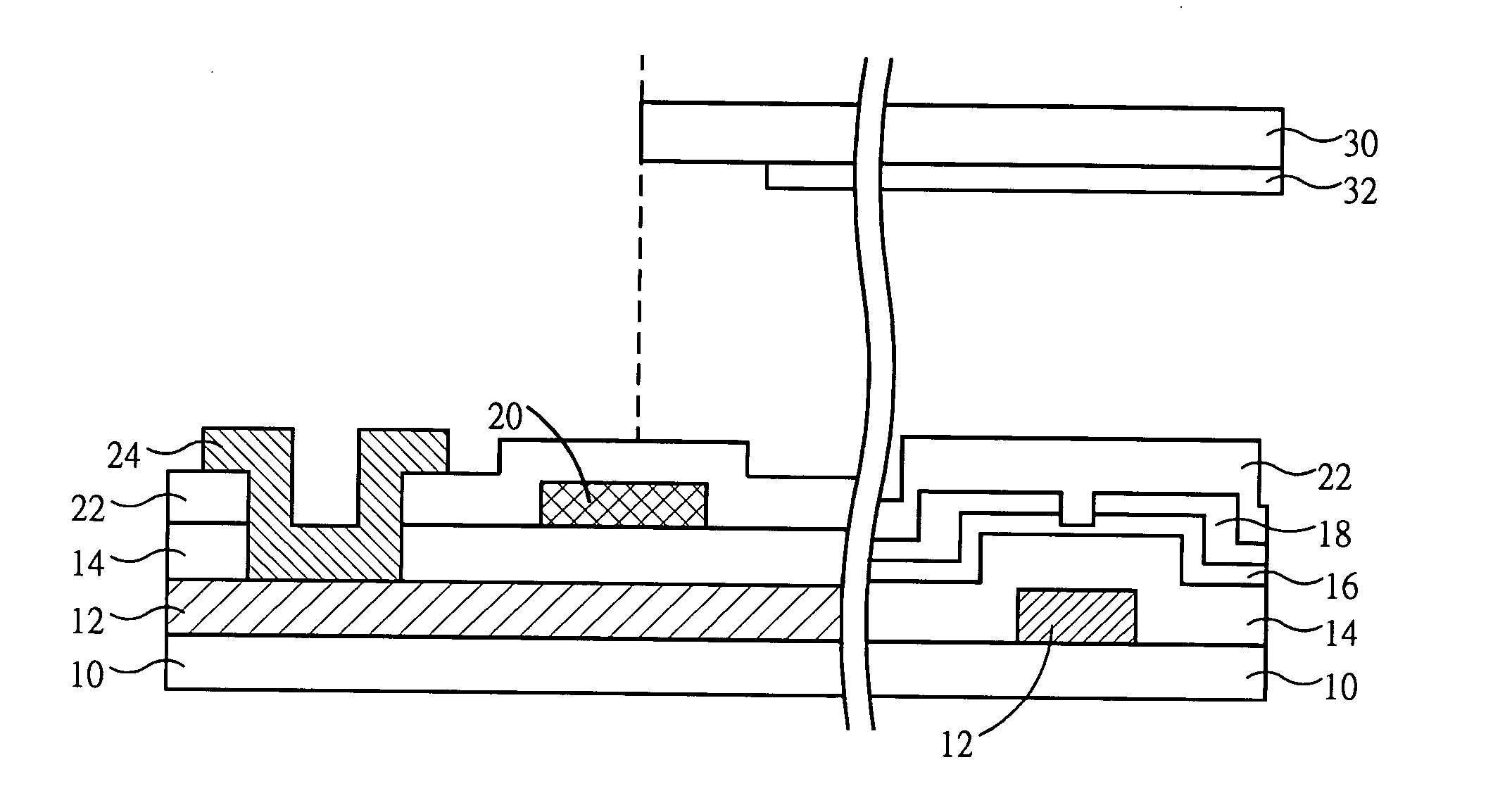
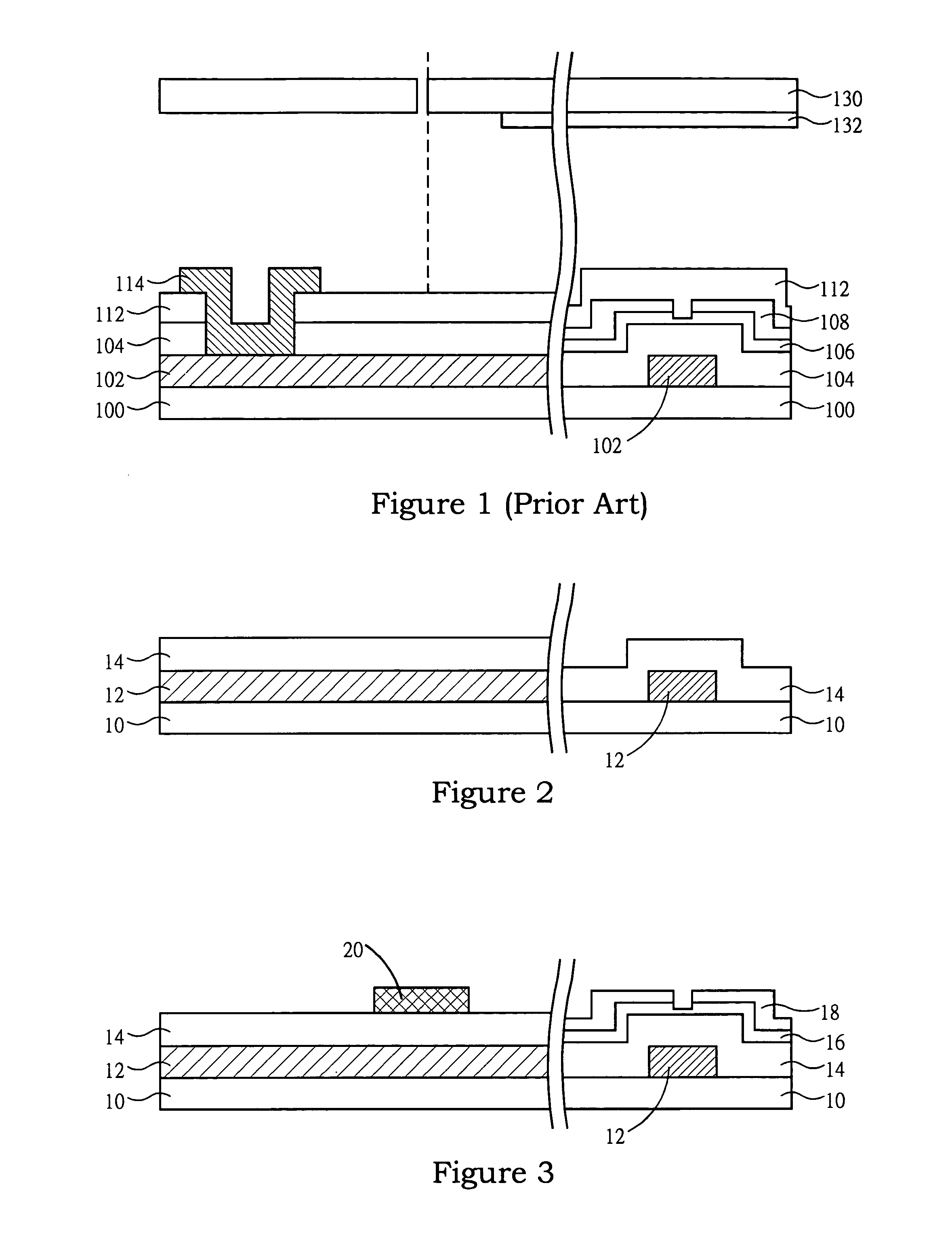
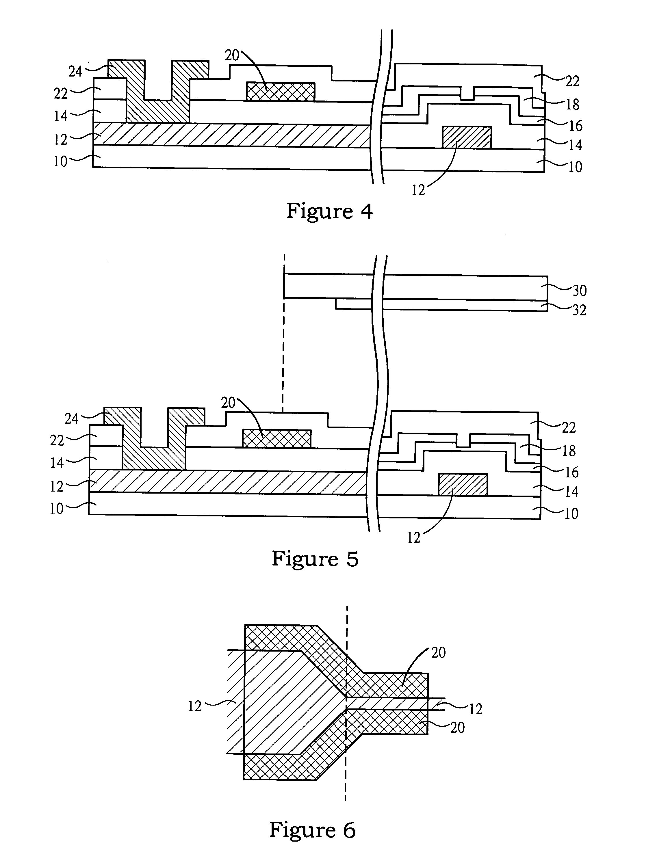
[0021] This invention provides a device for protecting a gate terminal and lead at stage of scribing and spalling a LCD panel, wherein the LCD panel comprises a first substrate with thin film transistor array thereon and a second substrate thereon within color filter opposite to the thin film transistor array. The device comprises a resist region covering the gate terminal and lead of gate electrode line and between a passivation layer and a gate insulating layer, and located at a scribing line on margin of the second substrate of the panel, thereby the resist region can protect the passivation layer and the gate insulating l...


PUM


Abstract

A resist region covering the gate terminal and lead of the gate electrode line and between a passivation layer and a gate insulating layer is used to protect the gate terminal and lead. The resist region is located at a scribing line on margin of the color filter substrate of a panel, thereby the resist region can protect the passivation layer and the gate insulating layer from cracking, and the gate terminal and the lead from corrosion after a portion of the color filter substrate is removed along the scribing line.

Description

BACKGROUND [0001] 1. Field of the Invention [0002] The present invention generally relates to a device and method for protecting gate terminal and lead, and more particularly to a device and method for protecting gate terminal and lead at stage of scribing and spalling. [0003] 2. Description of the Prior Art [0004] In fabrication of thin film transistor (TFT) liquid crystal display (LCD) device, an array substrate and a color filter substrate are provided respectively, in which thin film transistor array on the array substrate are formed by thin film deposition, lithographic process, and etching step of semiconductor process. Having been formed the two substrates, an assembling process, a scribing step, and a spalling step are performed. The scribing and spalling steps are to remove peripheral regions on the color filter substrate such that contact plugs of gate terminals on the array substrate can be exposed. [0005] The scribing and spalling steps can be shown in FIG. 1, wherein a ...

Claims


Application Information

Patent Timeline
IPC IPC(8): H01L21/77H01L21/84H01L27/12
CPCH01L27/1214H01L27/1288
Inventor CHU, HUNG-JENSHEN, HUI-CHUNG
Owner INTELLECTUAL VENTURES FUND 82
Why Eureka
Try Eureka