Measured object mounting tool and production method of three-dimensional shape data of dental prosthesis using that tool

a technology of three-dimensional shape data and measuring object, which is applied in the direction of mechanical measuring arrangements, impression caps, instruments, etc., can solve the problems of same shape, prosthesis cannot be moved, and prosthesis interferes with adjacent teeth, etc., and achieves the effect of short time and short tim

Inactive Publication Date: 2008-06-05
GC CORP
View PDF10 Cites 7 Cited by
  • Summary
  • Abstract
  • Description
  • Claims
  • Application Information

AI Technical Summary

Benefits of technology

[0023]Then, the further earnest work is carried out to solve the above problem of detecting the position of the upper end of the engaging portion from the three-dimensional shape data, when the model of the dental prosthesis and the measured object mounting tool are integrated and the boundary of each part cannot be distinguished. As a result of this, the followings were found out to complete the present invention. In this invention, instead of detecting such the position of the upper end of the engaging portion, the position of the lower end of an inclined part of the measured object mounting tool can be accurately detected by the steps of using a measured object mounting tool having the inclined part formed by a part of a conical shape at the boundary of the side face and the upper face of the cylindrical part, where the conical shape has an angle of 20 to 70 degrees with respect to a center axis of the cylindrical part, irradiating the laser light from the side face of the cylindrical part to the inclined part of the measured object mounting tool while keeping the state where the laser light is irradiated in parallel with the upper face of the cylindrical part, measuring a light receiving amount of the laser light, and defecting the position where the light receiving amount is remarkably decreased. Then, the three-dimensional coordinates of the portion other than the engaging portion of the model of the dental prosthesis can be accurately produced on the basis of the position of the lower end of the inclined part of the measured object mounting tool.
[0038]a measuring initial position moving step of keeping the laser light irradiated from the laser sensor to be in parallel to the upper face of the cylindrical part, moving the laser sensor along the Z axis direction by the measuring part so as to transfer the irradiated portion from the side face to the inclined part of the measured object mounting tool, detecting the position where the received light amount of the laser light is remarkably decreased, detecting the coordinate on the Z axis of the position of the lower end of the inclined part of the measured object mounting tool, calculating the coordinate on the Z axis of the position of the upper part of the engaging portion of the model of the dental prosthesis, on the basis of the prememorized distance on the Z axis between the positions of the lower end of the inclined part of the measured object mounting tool and the position of the upper end of the engaging portion of the model of the dental prosthesis, where the model of the dental prosthesis is provided on the measured object mounting tool, and moving quickly the laser sensor by the measuring part to the calculated position of the coordinate in the Z axis direction, and
[0042]Further, since the production method of the three-dimensional shape data of the dental prosthesis by using the measured object mounting tool according to the present invention comprises the following steps, the three-dimensional shape data of the dental prosthesis can be made in short time, when the length in the Z axis direction of the measured object mounting tool is comparatively short. The method comprises steps of a model mounted tool measuring step for rotating the rotary table around the Z axis as the axis thereof, keeping the laser light irradiated from the laser sensor to be in parallel with the upper face of the cylindrical part of the measured object mounting tool, moving the laser sensor by the measuring part in the Z axial direction so as to transfer the irradiated portion by laser light to the position of the height before reaching to the top of the pillar part of the measured object mounting tool from the side face of the cylindrical part of this tool passing through the inclined part of this tool, and rotationally moving the laser sensor for measuring the received light amount of the laser light from the cylindrical part and the pillar part of the measured object mounting tool and the model of the dental prosthesis, and the three-dimensional coordinate of these shapes, and a three-dimensional coordinate extracting step for detecting the position where the received light amount of the laser light is remarkably decreased when transferring from the side face to the inclined part of the cylindrical part of the measured object mounting tool, detecting the coordinate on the Z axis of the position of the lower end of the inclined part of the measured object mounting tool, calculating the coordinate on the Z axis of the position of the upper end of the engaging portion of the model of the dental prosthesis on the basis of the prememorized distance on the Z axis between the positions of the lower end of the inclined part of the measured object mounting tool and the upper end of the engaging portion of the model of the dental prosthesis, where the model of the dental prosthesis is provided on the measured object mounting tool, and extracting only the three-dimensional coordinates of the shape exclusive of the engaging portion of the model of the dental prosthesis positioned on the upper side from the coordinate calculated from the measured three-dimensional coordinate. Then, this method has the constitution of measuring at a stretch the received light amounts from the measured object mounting tool and the model of the dental prosthesis, and the three-dimensional coordinates of these shapes, and thereafter, detecting only the three-dimensional coordinates of the shape other than the engaging part of the model of the dental prosthesis. Thus, the method is preferable for making the three-dimensional shape data of the dental prosthesis in short time, when the length in the Z axis direction of the measured object mounting tool is comparatively short.
[0043]Further, since the production method of the three-dimensional shape data of the dental prosthesis by using the measured object mounting tool according to the present invention comprises the following steps, the three-dimensional shape data of the dental prosthesis can be made in short time, when the length in the Z axis direction of the measured object mounting tool is comparatively long. The method comprises the steps of a measuring initial position moving step of keeping the laser light parallel to the upper face of the cylindrical part, moving the laser sensor in the Z axis direction by the measuring part so as to transfer the irradiated portion by the laser light from the side face to the inclined part of the measured object mounting tool, detecting the point, where the received light amount of the reflected laser light is extremely decreased, to thereby detect the coordinate on the Z axis of the lower end of the inclined part of the measured object mounting tool, calculating the coordinate on the Z axis of the position of the upper end of the engaging portion of the model of the dental prosthesis, on the basis of the prememorized distance on the Z axis between the positions of the lower end of the inclined part of the measured object mounting tool and the upper end of the engaging portion of the model of the dental prosthesis, where the model of the dental prosthesis is provided on the measured object mounting tool, and moving quickly the laser sensor by the measuring part in the Z axis direction to the calculated position of the coordinate, and a model mounted tool measuring step of rotating and transferring the laser sensor while rotating the rotary table around the Z axis, measuring the three dimensional coordinates of the shape of the model of the dental prosthesis exclusive of its engaging portion. Then, the method has the constitution of measuring only the received light amount of the laser light of the measured object mounting tool, moving at a stretch the laser light to the upper end position of the engaging portion of the model of the dental prosthesis, that is, the initial measuring position, measuring only the three-dimensional coordinates of the shape other than the engaging portion of the model of the dental prosthesis. Thus, the method is preferable for making the three-dimensional shape data of the dental prosthesis in short time, when the length in the Z axis direction of the measured object mounting tool is comparatively long.
[0044]Further, in these production methods of the three-dimensional shape data of the dental prosthesis, when the center axis of the cylindrical part of the measured object mounting tool is not agreed beforehand with the Z axis, these axes can be easily adjusted by carrying out a both axes adjusting step for transferring the XY table in the X and / or the Y axis directions in order to agree the center axis of the cylindrical part of the measured object mounting tool to the Z axis, after carrying out the mounting tool placing step, whereby the measuring of the three-dimensional coordinates by the laser sensor of the measuring part, which is done in each step after this step, can be smoothly carried out, and the three-dimensional coordinates of the model of the dental prosthesis on the basis of the Z axis can be obtained. Thus the above step is preferable.

Problems solved by technology

However, the following problem was found.
Further, in a case of extracting the three-dimensional shape data of only the portion other than the engaging portion of the model of the dental prosthesis, since a position of an upper end of the engaging portion, which is the boundary of the engaging portion and the portion other than the engaging portion of the model of the dental prosthesis, cannot be accurately distinguished, if the three-dimensional shape data of a part, which is upper than the position of the upper end of the engaging portion, is extracted with slightly mistaking this position, the dental prosthesis having the same shape as that of the model of the dental prosthesis cannot be made.
Thus, when the produced dental prosthesis is actually mounted, there are problems that the dental prosthesis interferes to an adjacent tooth, the position of an occlusal face cannot be the right position, and the dental prosthesis cannot be mounted well with the implant fixture.
Further, more particularly, when the produced dental prosthesis is the above-mentioned abutment, there is a problem that aesthetic appreciation is remarkably damaged since the abutment is not fitted to a shape of a gingiva of a patient, the abutment itself is seen from the upper side of the gingiva, or the abutment is embedded into the gingiva.

Method used


Image

  • Measured object mounting tool and production method of three-dimensional shape data of dental prosthesis using that tool
  • Measured object mounting tool and production method of three-dimensional shape data of dental prosthesis using that tool
  • Measured object mounting tool and production method of three-dimensional shape data of dental prosthesis using that tool

Examples


Embodiment Construction

[0056]Hereinafter, the production method of the three-dimensional shape data of the dental prosthesis according to the present invention is concretely explained with drawings.

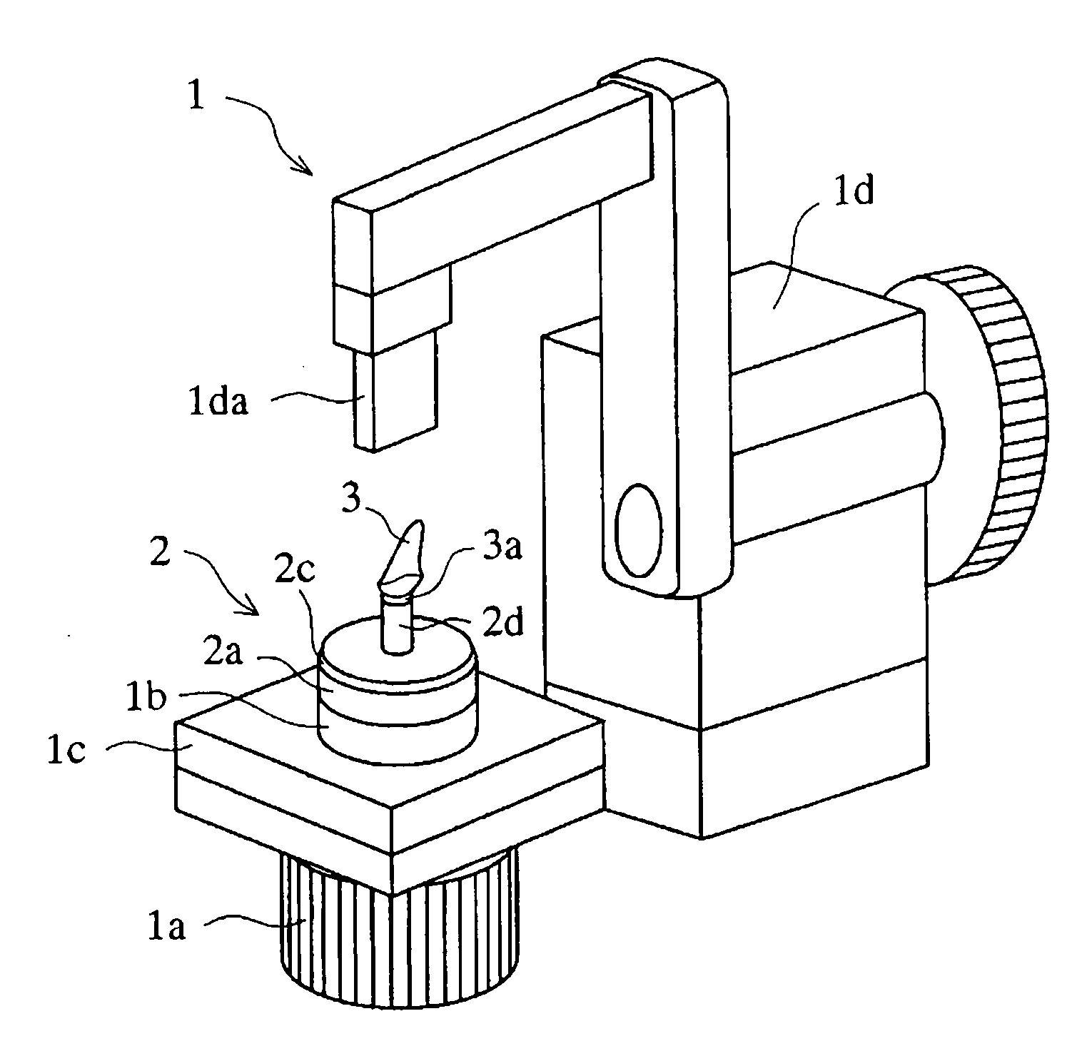
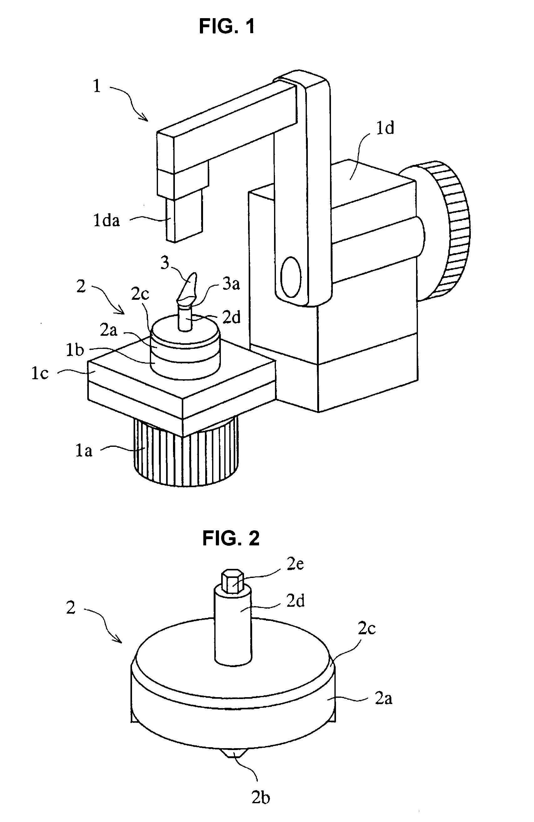
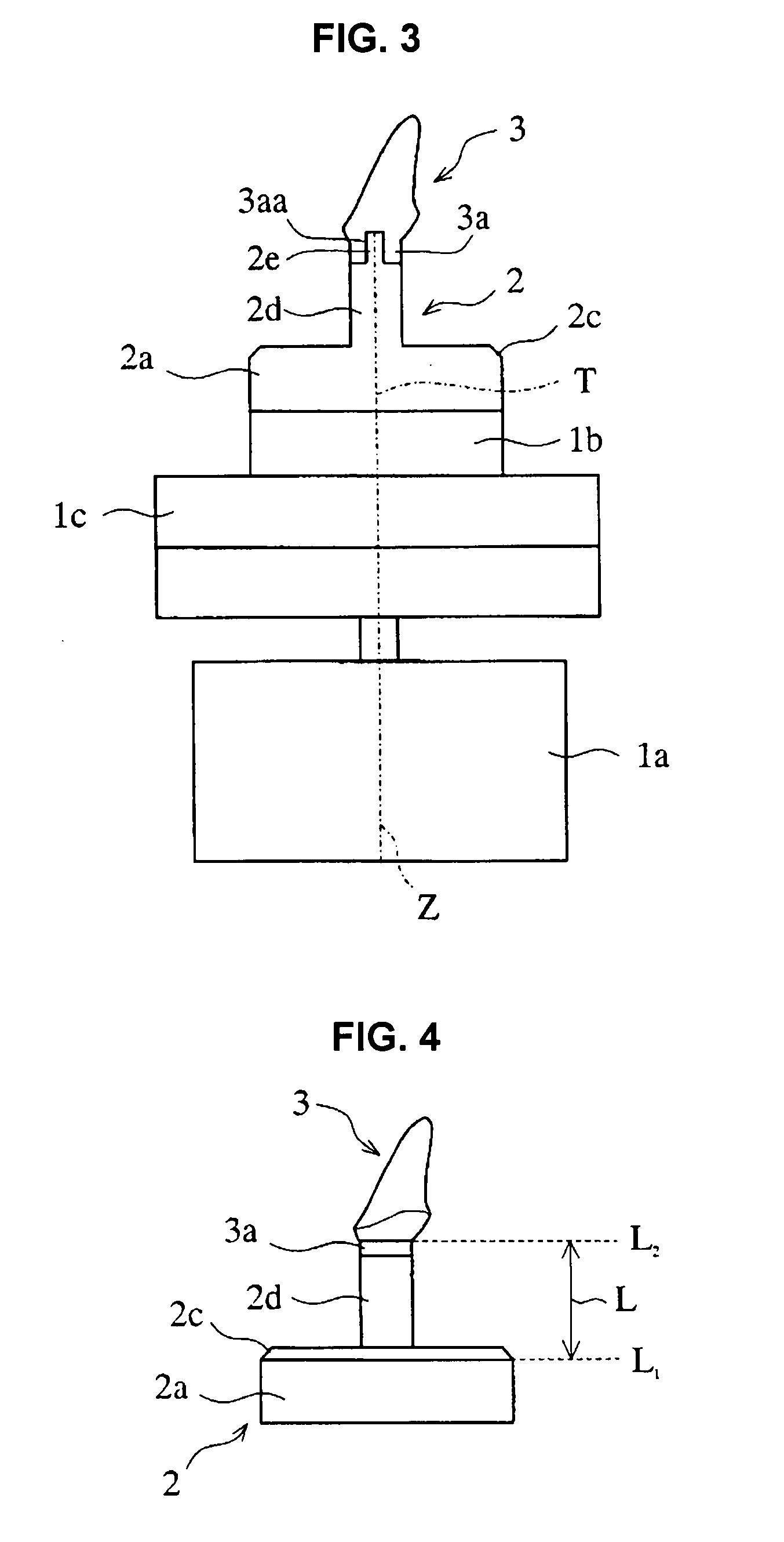
[0057]FIG. 1 is a perspective explanation view schematically illustrating one example of a three-dimensional measuring device used in the present invention. FIG. 2 is a perspective enlarged explanation view illustrating a shape of an upper part of a measured object mounting tool removed from the placing table of the three-dimensional measuring device illustrated in FIG. 1. FIG. 3 is a sectional explanation view schematically illustrating the state where the center axis of the cylindrical part of the measured object mounting tool is agreed with the Z axis. FIG. 4 is a front explanation view schematically illustrating a positional relationship between a lower end position of an inclined part of the measured object mounting tool and an upper end position of an engaging portion of a model of a dental prosthesis in ...


PUM


Abstract

A measured object mounting tool 2 for producing a three-dimensional shape data comprises a placing part 2b at the lower face of a cylindrical part 2a, an inclined part 2c at a boundary between the side face and the upper face of the cylindrical part 2a, and a pillar part 2d at the upper face of the cylindrical part 2a, where the pillar part 2d has a mounting part 2e at the upper face thereof, a three-dimensional coordinate other than the engaging portion 3a of a model 3 is produced by engaging the model of the dental prosthesis with the mounting part 2e of the tool 2 on a placing table 1; detecting a position where a received light amount is remarkably decreased to by a laser sensor detect a lower end of the inclined part 2c; and thereby calculating an upper end of the engaging portion 3a.

Description

CROSS-REFERENCE TO RELATED APPLICATIONS[0001]This application is a Divisional of and claims the benefit of priority under 35 U.S.C. §120 from U.S. Ser. No. 11 / 259,140, filed Oct. 27, 2005, and claims the benefit of priority under 35 U.S.C. § 119 from prior Japanese Patent Applications No. 2004-314485, filed Oct. 28, 2004, the entire contents of each of which are incorporated herein by reference.BACKGROUND OF THE INVENTION[0002]1. Field of the Invention[0003]The present invention relates to a measured object mounting tool used for placing a model of a dental prosthesis when three-dimensional coordinates of a shape of the model of the dental prosthesis, which is a measured object, are measured by a three-dimensional measuring device. Further, the present invention relates to a production method of three-dimensional data of a dental prosthesis for cutting a block when cutting the dental prosthesis by an automatic cutting machine using the measured object mounting tool so as to have the...

Claims


Application Information

Patent Timeline
Patent Type & Authority Applications(United States)
IPC IPC(8): A61C19/04
CPCA61C9/004G01B11/24A61C13/0004A61C9/0053A61C9/0093A61C5/77A61C13/0003
Inventor MATSUDA, YOSHINORISAKAMOTO, YUUKIEBIHARA, YOSHINORI
Owner GC CORP
Why Eureka
Try Eureka