Electrically Conductive Component Suited for Use in Access Control Devices

a technology of electrically conductive components and access control devices, which is applied in the direction of coupling device connections, conductor screwing into other parts, and locking applications, etc., can solve the problems of easy damage and difficult installation of cables, and achieve the effect of increasing the durability of locks and facilitating installation

Active Publication Date: 2008-06-05
DORMAKABA USA INC
View PDF13 Cites 18 Cited by
  • Summary
  • Abstract
  • Description
  • Claims
  • Application Information

AI Technical Summary

Benefits of technology

[0007]It is a further aim of the present invention to eliminate the need to resort to power transmission cables,

Problems solved by technology

Cables are typically difficult to

Method used


Image

  • Electrically Conductive Component Suited for Use in Access Control Devices
  • Electrically Conductive Component Suited for Use in Access Control Devices
  • Electrically Conductive Component Suited for Use in Access Control Devices

Examples


Embodiment Construction

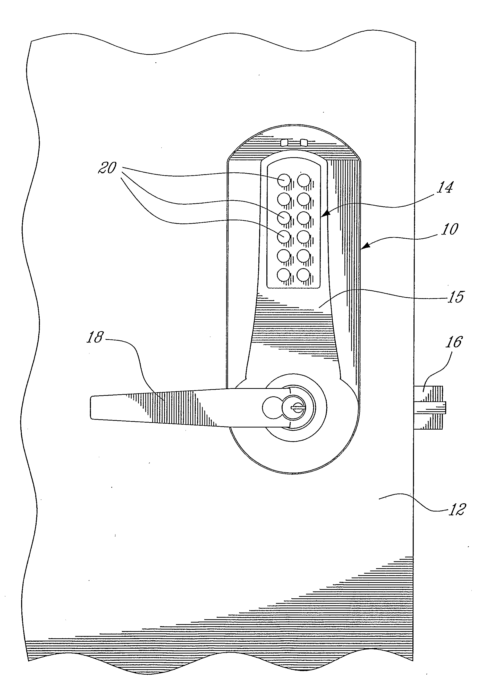
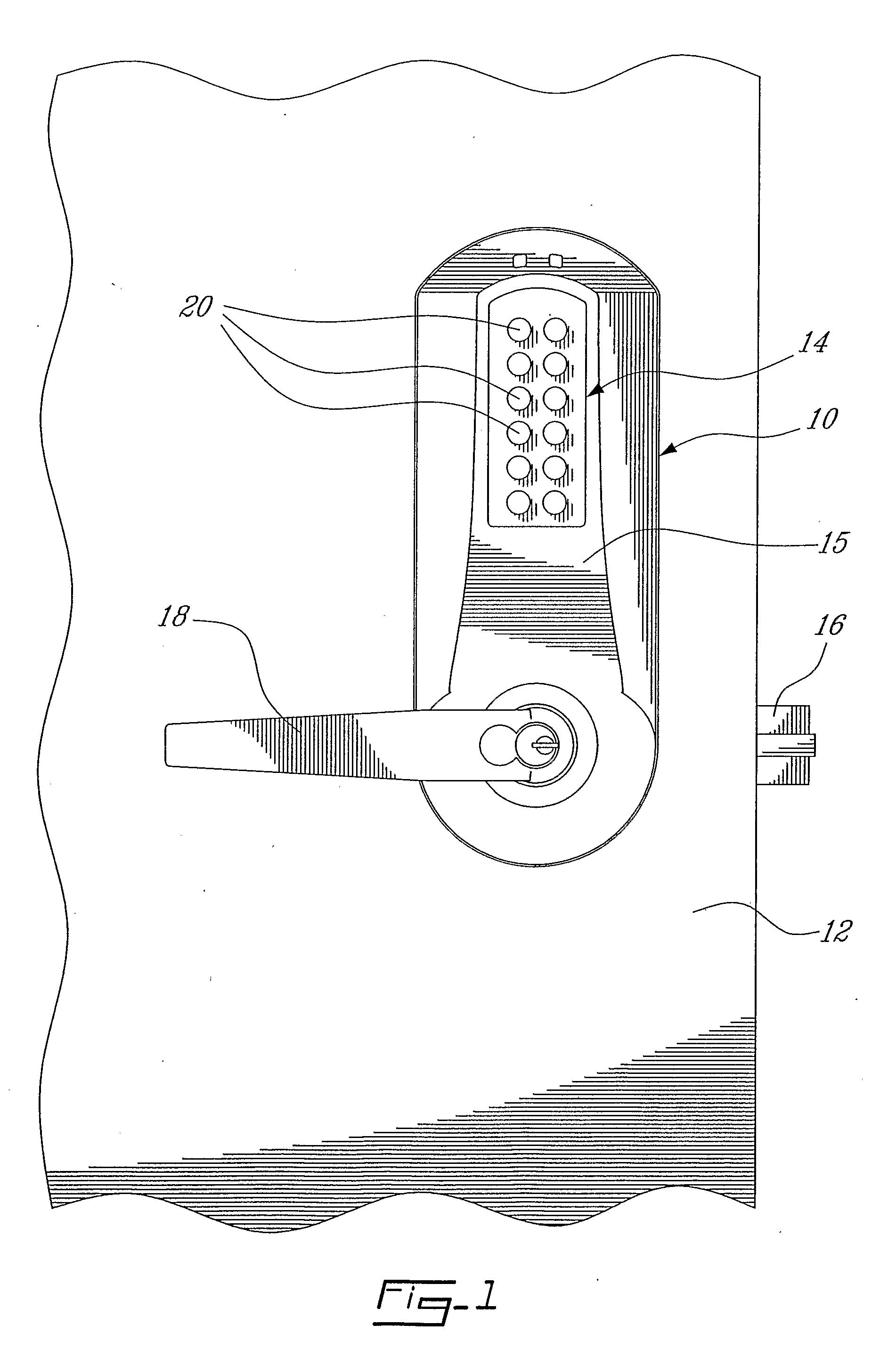
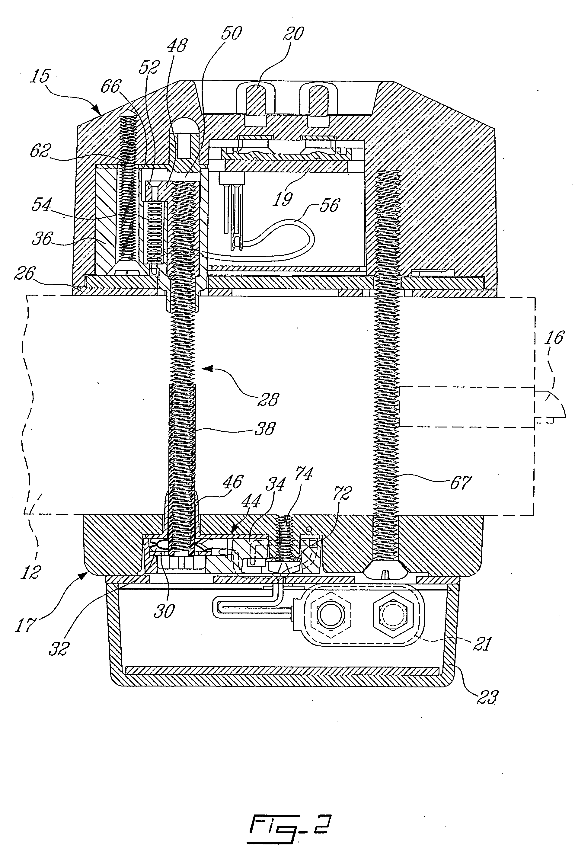
[0016]FIGS. 1 and 2 show a lock 10 mounted to a door 12 for selectively preventing and enabling opening of the door 12. The lock 10 comprises an electronic access control device 14 adapted to control the operation of a latch bolt 16. The term “door” is herein intended to mean any surface upon which an access control device can be mounted.

[0017]As shown in FIGS. 2 and 3, the access control device 14 has an outdoor housing component 15 and an indoor housing component 17 adapted to be respectively mounted on the outer and inner side of the door 12. The outdoor housing component 15 houses an electronic control unit 19 (FIG. 2) operational for allowing or preventing retraction of latch bolt 16 by manual operation of a handle 18 (FIG. 1). The electronic control unit 19 typically includes a circuit board operatively associated to a number of data entry key buttons 20 (FIGS. 1 and 2) for activation to enter combination and initialization data, as is well known in the art. The entry buttons ...


PUM


Abstract

An access control device (10) has an electronic/electric control unit (19) fed with electrical current via an electrically conductive fastener (28), such as the ones that also function to clamp the outdoor and indoor housings (15, 17) of the device (10) together against the opposed sides of a door (12) or the like.

Description

BACKGROUND OF THE INVENTION[0001]1. Field of the Invention[0002]The present invention generally relates to electrical current transmission and, more particularly, to a new way of transferring electrical current from one component to another.[0003]2. Description of the Prior Art[0004]Electro-mechanical and electronic access control devices, commonly referred to as “locks” need a source of power to operate the electronics that decode inputs caused by persons attempting access and also to provide motive force for initiating unlocking. The prior art includes various methods of providing power internal to the access control device, such as primary and secondary batteries, dynamo generators, piezoelectric generators and solar cells. External sources of power are also employed, such as voltage stepped down from 120 VAC household current. For external power, the prior art includes wiring directly to the access control device or wiring to the strike area in the door frame then transferring t...

Claims


Application Information

Patent Timeline
IPC IPC(8): H01R4/00E05B47/00H01R4/56
CPCE05B49/00H01R9/18H01R4/304Y10T70/7062
Inventor CRAIG, CLARK EDGAR
Owner DORMAKABA USA INC
Why Eureka
Try Eureka