
System and Method for Implementing a Unified Model for Integration Systems

a technology of integration system and model, applied in the field of system and method for implementing a unified model for integration system, can solve the problems of inability to provide continuous application solutions, existing art has artificial distinctions that produce substantial redundancy, and the selection of a system and model to use for designing an application may not always be clear to a solution archi

Inactive Publication Date: 2008-06-05
LINKEDIN
View PDF49 Cites 43 Cited by
  • Summary
  • Abstract
  • Description
  • Claims
  • Application Information

AI Technical Summary

Benefits of technology

[0016]In one embodiment, the system, method, and program product specify the first operator and the second operator as independent processing constructs.
[0015]In one embodiment, the system, method, and program product compile the dataflow diagram into sequential executable code. In another embodiment the system, method, and program product include a meta-state at the first operator that corresponds to a current processing state associated with the computations performed on the plurality of data items included in the particle. In yet another embodiment, the system, method, and program product express a control dependency between a plurality of activities.
[0018]In one embodiment, the system, method, and program product use the dataflow diagram to correspond to a batch data processing application. In another embodiment, the system, method, and program product use the dataflow diagram to correspond to a stream data processing application. In yet another embodiment, the system, method, and program product use the dataflow diagram to correspond to an event processing application. In yet another embodiment, the system, method, and program product include graphical notations in the data flow diagram. In yet another embodiment, the system, method, and program product include a non-graphical language implementation in the data flow diagram.
[0019]The foregoing is a summary and thus contains, by necessity, simplifications, generalizations, and omissions of detail; consequently, those skilled in the art will appreciate that the summary is illustrative only and is not intended to be in any way limiting. Other aspects, inventive features, and advantages of the present invention, as defined solely by the claims, will become apparent in the non-limiting detailed description set forth below.

Problems solved by technology

A challenge found is that existing art has artificial distinctions that produce substantial redundancy.
In addition, existing art does not provide a solution for continuous applications.
Another challenge found is that each of the existing models has disadvantages compared to the other models and, therefore, selecting a system and model to use for designing an application may not always be clear to a solutions architect.
In addition, many solutions may not be accomplished using existing models because of their disadvantages.
As a result, a solutions architect may require a custom solution that is both expensive to develop and maintain.
Furthermore, custom solutions are typically lower quality because the packaged software undergoes more rigorous testing.

Method used


Image

  • System and Method for Implementing a Unified Model for Integration Systems
  • System and Method for Implementing a Unified Model for Integration Systems
  • System and Method for Implementing a Unified Model for Integration Systems

Examples


Embodiment Construction

[0035]The following is intended to provide a detailed description of an example of the invention and should not be taken to be limiting of the invention itself. Rather, any number of variations may fall within the scope of the invention, which is defined in the claims following the description.

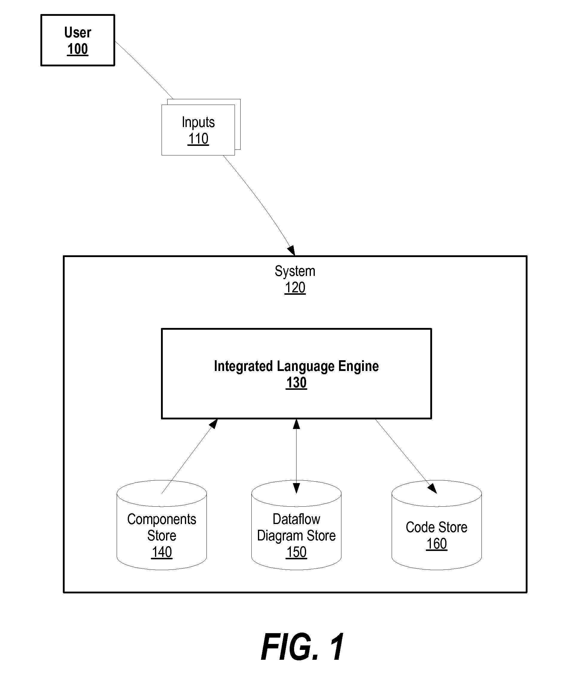
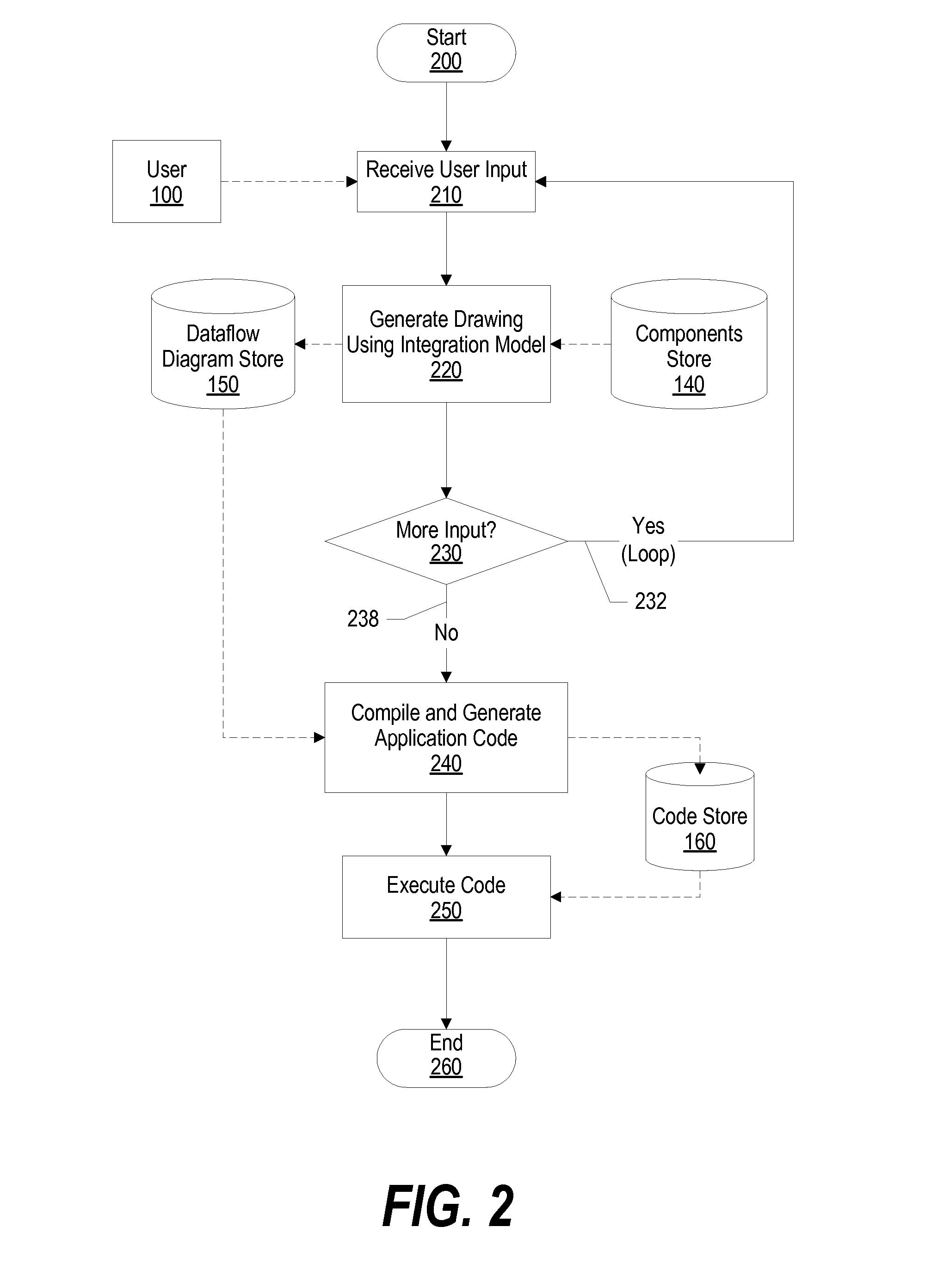
[0036]FIG. 1 is a diagram showing a user creating a dataflow diagram based upon a unified integration model. User 100 provides inputs 110 to integrated language engine 130, which uses a unified integration model to generate a dataflow diagram. In turn, integrated language engine 130 compiles the dataflow diagram to create application code.

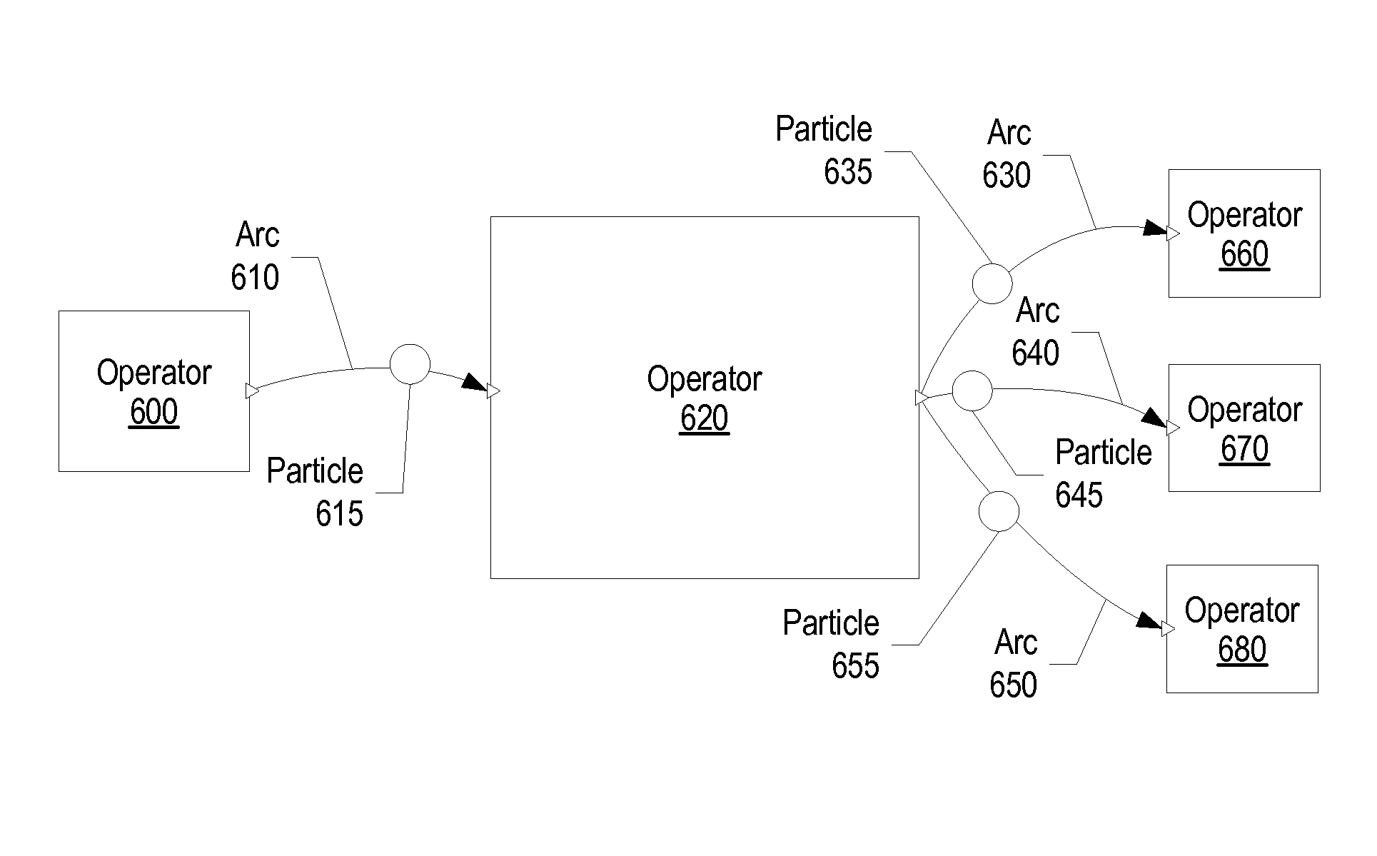
[0037]System 120 includes integrated language engine 130, components store 140, dataflow diagram store 150, and code store 160. Integrated language engine 130 receives inputs 110 from user 100 for creating a dataflow diagram. A dataflow diagram is a directed acyclic graph that includes components such as operators, arcs, and blocks to express an application. ...


PUM


Abstract

A system and method for implementing a unified model for integration systems is presented. A user provides inputs to an integrated language engine for placing operator components and arc components onto a dataflow diagram. Operator components include data ports for expressing data flow, and also include meta-ports for expressing control flow. Arc components connect operator components together for data and control information to flow between the operator components. The dataflow diagram is a directed acyclic graph that expresses an application without including artificial boundaries during the application design process. Once the integrated language engine generates the dataflow diagram, the integrated language engine compiles the dataflow diagram to generated application code.

Description

BACKGROUND OF THE INVENTION[0001]1. Technical Field[0002]The present invention relates to a system and method for implementing a unified model for integration systems. More particularly, the present invention relates to a system and method for using a unified model for expressing an application in a dataflow diagram without artificial boundaries that, in turn, allows for greater application optimization.[0003]2. Description of the Related Art[0004]Applications in the integration world are typically distinguished in categories such as Batch, Transactional and Continuous. Batch Integration Applications (IA) are mostly used where a new integrated solution replaces obsolete custom-built disparate applications and migration of the existing data is required. Transactional IA emerged mainly in the form of Business Process Management (BPM), where various applications implement a business process by exchanging requests and replies with each other under transaction guarantees. And, continuous...

Claims


Application Information

Patent Timeline
IPC IPC(8): G06F9/44G06F9/45
CPCG06F8/433G06F8/34
Inventor BAR-OR, AMIRBECKERLE, MICHAEL JAMES
Owner LINKEDIN
Learn More