Method and system for detecting movement of an object

a technology of object movement and detection method, applied in the field of contactless user interface for electronic equipment, can solve the problems of affecting the user's periodic typing on the computer, affecting the user's typing experience, and requiring a long distance for the mouse to move,

Inactive Publication Date: 2008-06-05
SONY ERICSSON MOBILE COMM AB
View PDF13 Cites 393 Cited by
  • Summary
  • Abstract
  • Description
  • Claims
  • Application Information

AI Technical Summary

Benefits of technology

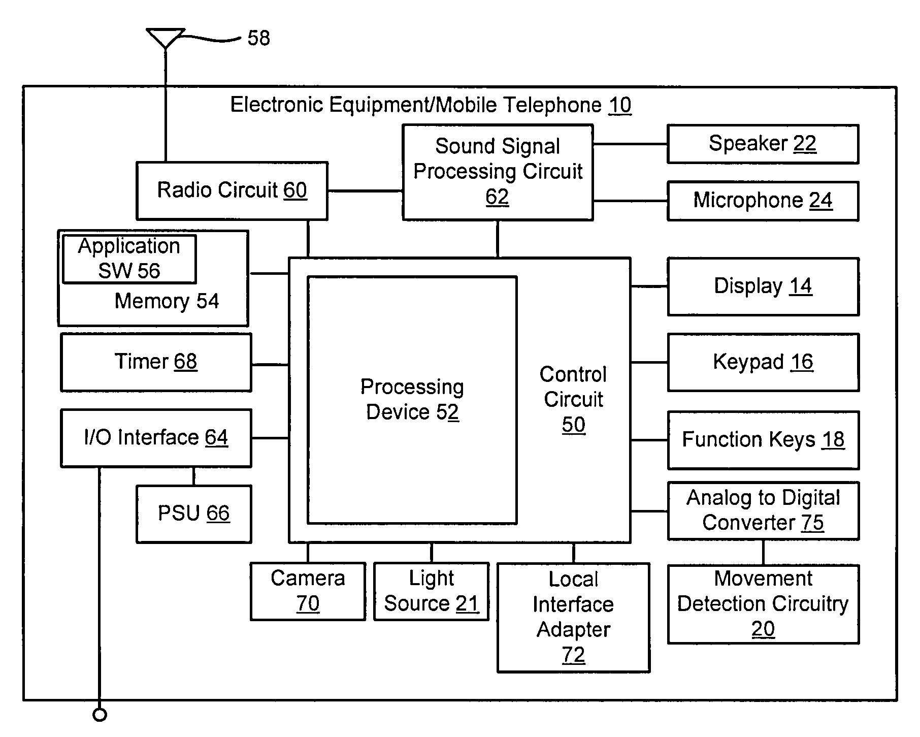
[0046]It should be emphasized that the term “comprise / comprising” when used in this specification is taken to specify the presence of stated features, integers, steps or components but does not preclude the presence or addition of one or more other features, integers, steps, components or groups thereof.”The term “electronic equipment” includes portable radio communication equipment. The term “portable radio communication equipment”, which herein after is referred to as a mobile radio terminal, includes all equipment such as mobile telephones, pagers, communicators, i.e., electronic organizers, personal digital assistants (PDA's), portable communication apparatus, smart phones or the like.

Problems solved by technology

The growing popularity of laptop or notebook computers has created a significant problem for mouse type technologies that require a rolling surface.
Adding to the problem is that a mouse usually needs to be moved over long distances for reasonable resolution.
Finally, a mouse requires the user to lift a hand from the keyboard to make the cursor movement, thereby disrupting and / or otherwise preventing a user from periodically typing on the computer.
A track ball is generally large in size and does not fit well in a volume-sensitive application such as a laptop computers or other small and / or portable electronic equipment.
There are drawbacks associated with user interfaces that require physical contact.
Such drawbacks include, densely populated user interfaces, difficult manipulation of the user interface due to physical size limitation of electronic equipment, difficult for users to view and / or otherwise manipulate densely populated user interfaces, etc.

Method used


Image

  • Method and system for detecting movement of an object
  • Method and system for detecting movement of an object
  • Method and system for detecting movement of an object

Examples


example 1

Reject / Mute Call

[0093]Referring to FIG. 15, at step 100, the electronic equipment receives a call and / or message. At step 102, a signal is output to the associated user to indicate receiving an incoming call and / or message. At step 104, movement detection circuitry 20 is activated. Optionally, a gesture and / or movement control icon may also appear on a display, which is visible to the user to indicate to the user that the movement detection circuitry 20 is active. In addition, one or more light emitting diodes (LEDs) and / or display lights may fade in to illuminate at least a portion of the movement detection circuitry 20. At step 106, a user action is detected based on periodically acquired information from the movement detection circuitry 20. In this embodiment, acquired movement detection data may correspond to an exemplary mute function and / or exemplary reject function. For example, an object (e.g., an associated user's hand) is detected moving downward over the movement detectio...

example 2

Snooze Alarm

[0094]Another exemplary method in accordance with aspects of the invention is illustrated at FIG. 18. Referring to FIG. 18, at step 120, an alarm housed in electronic equipment 10 is set to sound at a certain time. At step 122, movement detection circuitry 20 is activated at the time of the alarm sounds. Optionally, a gesture and / or movement control icon may also appear on a display, which is visible to the user to indicate to the user that the movement detection circuitry 20 is active. In addition, one or more light emitting diodes (LEDs) and / or display lights may fade in to illuminate at least a portion of the movement detection circuitry 20. At step 124, a user action is detected that corresponds to a “snooze” function. The snooze function stops the alarm and sets it to ring again at a short time later, typically anywhere between five and ten minutes. For example, an object (e.g., an associated user's hand) is detected moving downward over the movement detection circu...

example 3

Adjust Volume

[0095]The volume of an audio signal output from the electronic equipment and / or an external speaker and / or device coupled to the electronic equipment may also be controlled by detecting an object moving in the field of the movement detection circuitry 20. In this example, it is assumed that the electronic equipment is outputting an audio stream through a speaker. The speaker may be internal to the electronic equipment or external to the electronic equipment. Referring to FIG. 19, at step 140, an electronic equipment 10 is provided that outputs audio through a speaker. Upon activation of the audio output, at step 142, movement detection circuitry 20 is activated. Optionally, a gesture and / or movement control icon may also appear on a display, which is visible to the user to indicate to the user that the movement detection circuitry 20 is active. In addition, one or more LEDs and / or display lights may fade in to illuminate at least a portion of the movement detection circ...


PUM


Abstract

A system, method and computer application for electronic equipment 10 having a contact-less user input device that is capable of detecting and/or sensing user movement (e.g., gestures) and controlling one or more parameters associated with the electronic equipment and/or being executed on the electronic equipment based at least in part on the detected and/or sensed user movement is disclosed. A predetermined movement may be detected by the movement detection circuitry (e.g., camera, infrared sensors, etc.) and a corresponding user controllable feature or parameter of the electronic equipment and/or application program may be controlled based upon the detected predetermined movement. The controllable feature may vary based upon the type of application being executed by the electronic equipment and velocity and/or acceleration of the object being detected.

Description

RELATED APPLICATION DATA[0001]This application claims the benefit of U.S. Provisional Application No. 60 / 868,660 filed Dec. 5, 2006, which is incorporated herein by reference.TECHNICAL FIELD OF THE INVENTION[0002]The present invention relates to a contact-less user interface for electronic equipment that is capable of detecting movement of an object and controlling one or more parameters associated with the electronic equipment and / or applications executed on the electronic equipment based at least in part on the detected movement of the object.DESCRIPTION OF THE RELATED ART[0003]Electronic equipment, such as, for example, communication devices, mobile phones, personal digital assistants, etc. are typically equipped to communicate over cellular telephone communication networks. Such electronic equipment generally includes one or more user input devices. Common input devices include, for example, a computer mouse, a track ball, a touchpad, etc. The computer mouse is widely popular as...

Claims


Application Information

Patent Timeline
Patent Type & Authority Applications(United States)
IPC IPC(8): G06F3/033
CPCG06F3/017
Inventor MOVOLD, CATHRINEJONSSON, MARTEN A.MAURITZSON, LARS D.KLINGHULT, GUNNARMEIBY, JOHANNA L.
Owner SONY ERICSSON MOBILE COMM AB
Why Eureka
Try Eureka