

Sewing machine
- Summary
- Abstract
- Description
- Claims
- Application Information
AI Technical Summary
Benefits of technology
Problems solved by technology
Method used
Image

Examples
first exemplary embodiment
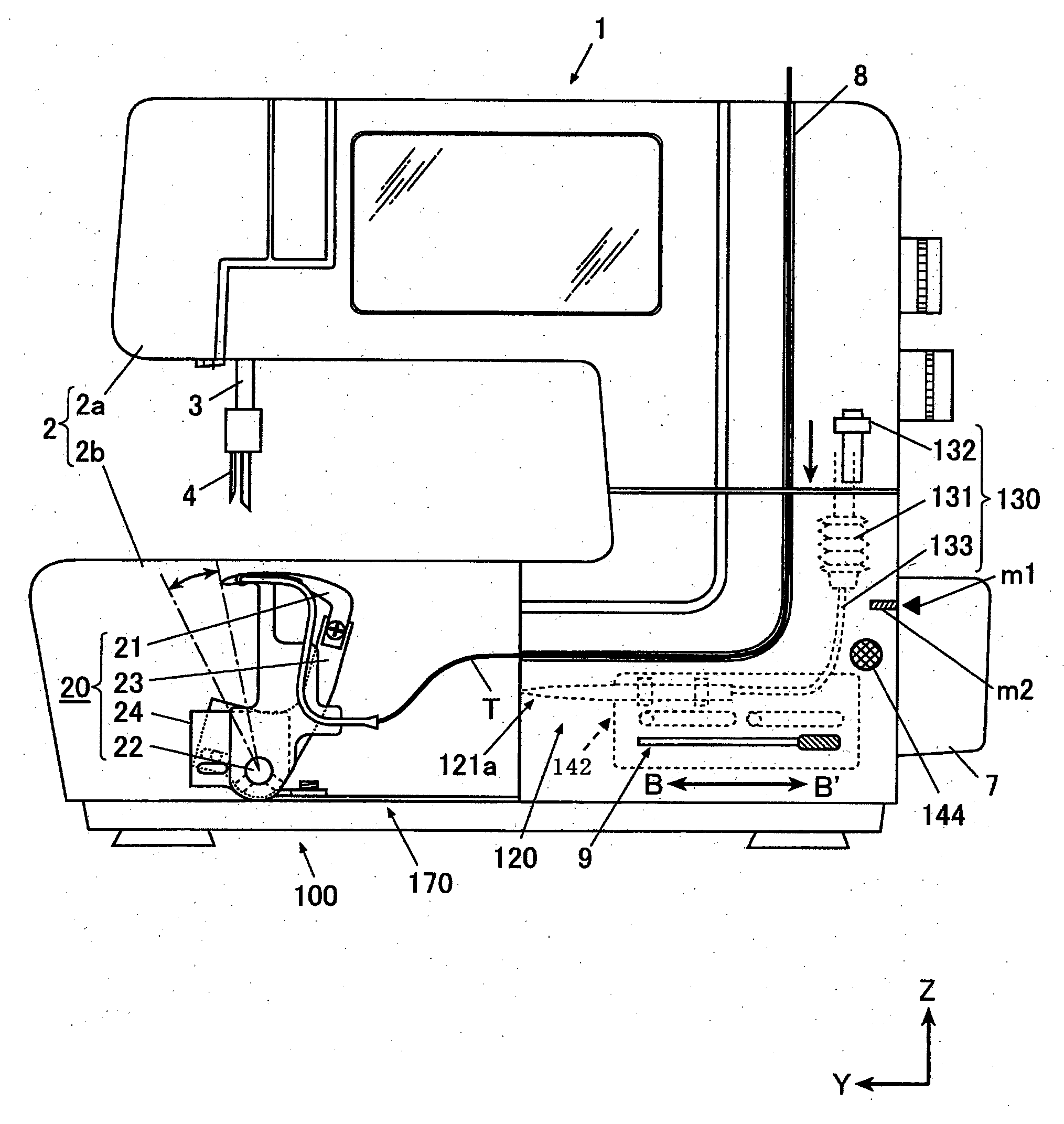
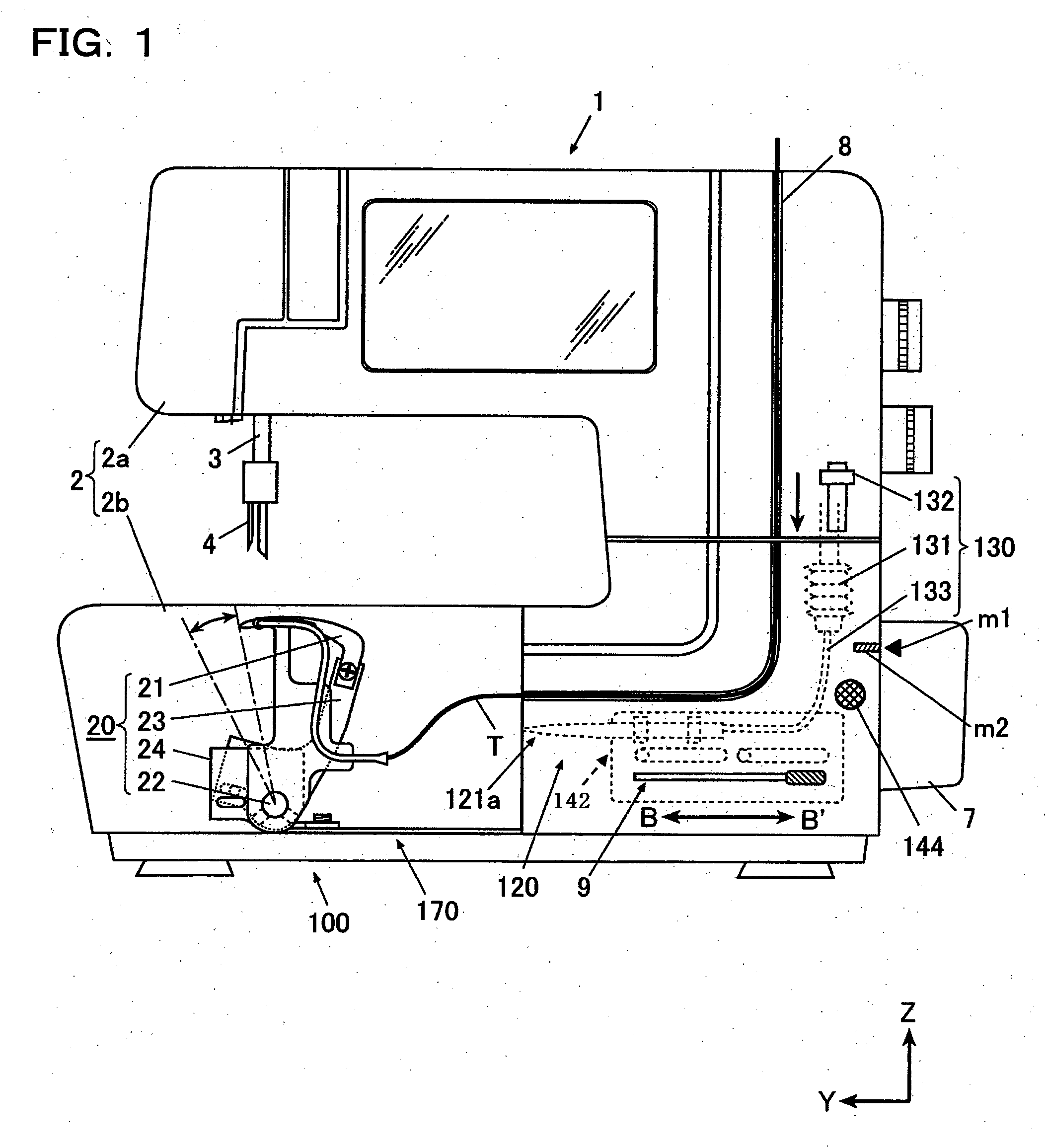
[0037]As shown in FIG. 1, a sewing machine 1 (a double chainstitch sewing machine) includes a needle driving mechanism (not shown) which drives sewing needles 4 (needles) with a motor 5 (see FIGS. 10 and 11), a looper driving mechanism 20 having a looper 21 which forms a seam by cooperating with the needles 4, and a threading device 100 which inserts a looper thread T through a thread hole 21b of the looper 21. Each portion will be described below in detail.
Needle Driving Mechanism
[0038]The needle driving mechanism (not shown) includes an upper shaft (not shown) which is rotated by the motor 5, and a vertical motion transmitting mechanism which converts a rotating motion of the upper shaft into a vertical reciprocating motion through a rotating weight and a crank rod and transmits the vertical reciprocating motion to a needled bar 3. Two needles 4 are held on a lower end of the needle bar 3. When the upper shaft is rotated by a driving operation of the motor 5, the vertical motion i...
second exemplary embodiment
[0094]Next, a second exemplary embodiment of the invention will be described in detail with reference to FIGS. 7 and 8. In the following exemplary embodiments, the structures that are the same as those in the first exemplary embodiment have will be labeled with the same reference numerals, and repetitive description thereof will be omitted.
[0095]The second exemplary embodiment is different from the first exemplary embodiment in that a lever 244 (operation input means, a manual operating portion) and a main shaft locking mechanism 260 which is driven by the lever 244 are provided.
[0096]As shown in FIG. 8, the lever 244 is supported on a frame 2 rotatably in a horizontal direction through a shaft 244a in a middle in a longitudinal direction thereof. One end of the lever 244 is protruded from a lever groove 9 (see FIG. 1) provided on a side surface of a bed portion 2b of the frame 2 in the Y-axis direction to a working position side of an operator (this side of the paper in FIG. 1) (no...
third exemplary embodiment
[0105]Next, description will be given to a third exemplary embodiment of the invention. As shown in FIG. 9, a main shaft locking mechanism 360 according to the third exemplary embodiment includes a motor starting switch 361 (motor driving input means), a motor stopping switch 362 (detecting means) which detects that the main shaft locking mechanism 360 positions a lower shaft 6 at a predetermined rotating angle, and a control portion 350 (motor control means) which inputs a start of a rotating and driving operation to a motor 5 when the main shaft locking mechanism 360 is brought into an operable state in accordance with an input operation from a lock button 144 (operation input means), and inputs a stop of the rotating and driving operation of the motor 5 when the lower shaft 6 is positioned at the predetermined rotating angle differently from the first and second exemplary embodiments.
[0106]The motor starting switch 361 can carry out ON / OFF switching by opening / closing a detecting...
PUM
 Abstract
Description
Claims
Application Information