Mold cooling by recovery of energy from spent compressed air in blow-molding process

a blow molding and compressed air technology, applied in other chemical processes, refrigeration machines, lighting and heating apparatus, etc., can solve the problems of waste of compressed gas used in blow molding process, scale buildup and corrosion of water-cooled systems, and high maintenance costs, and achieve the effect of less energy

Inactive Publication Date: 2008-06-12
NESTLE WATERS NORTH AMERICA
View PDF10 Cites 31 Cited by
  • Summary
  • Abstract
  • Description
  • Claims
  • Application Information

AI Technical Summary

Benefits of technology

[0006]The present invention provides a system and method for cooling a blow-molding machine using less energy. The invention also achieves the result of recovering otherwise-wasted energy from the compressed gas used for blowing the mold and operating the machine. The recovered energy is used for cooling the mold.

Problems solved by technology

Water-cooled systems are subject to scale buildup and corrosion, are expensive to maintain and require a supply of external energy to chill the water, while the energy contained in the compressed gas used in the blow-molding process is wasted, as the compressed gas is simply vented to the ambient environment.

Method used


Image

  • Mold cooling by recovery of energy from spent compressed air in blow-molding process
  • Mold cooling by recovery of energy from spent compressed air in blow-molding process
  • Mold cooling by recovery of energy from spent compressed air in blow-molding process

Examples


Embodiment Construction

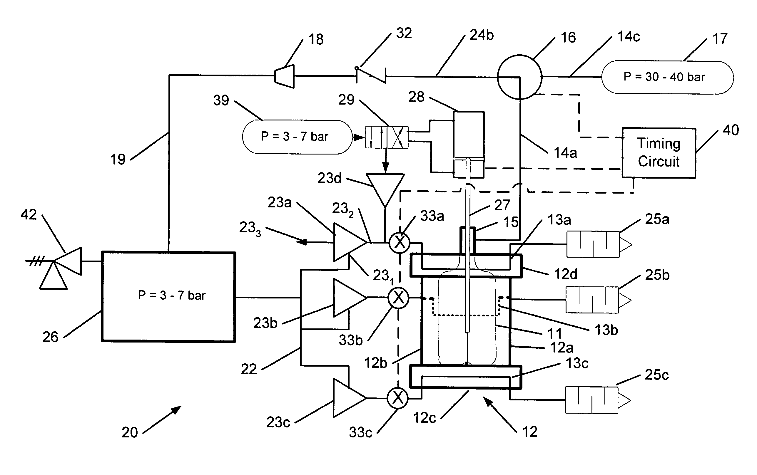
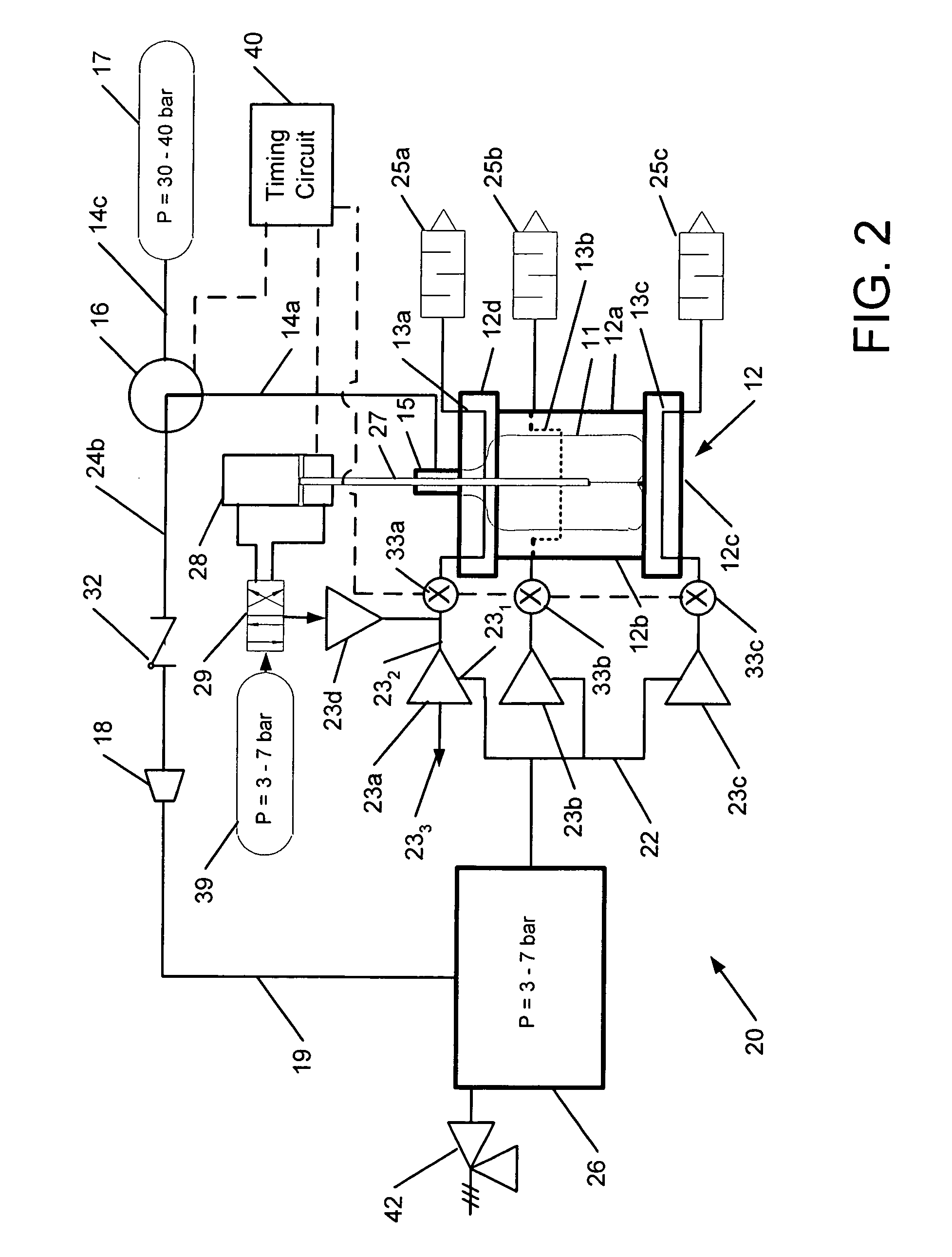
[0019]The invention is directed to systems and methods that efficiently cool a mold at the conclusion of the molding process to facilitate removal of a dimensionally stable container from the mold. In particular, the systems and methods described herein can recover energy from the compressed gas employed in the blow-molding process. The recovered energy is used for cooling the mold, thereby saving energy compared to conventional cooling methods that employ recirculating chilled water cooling.

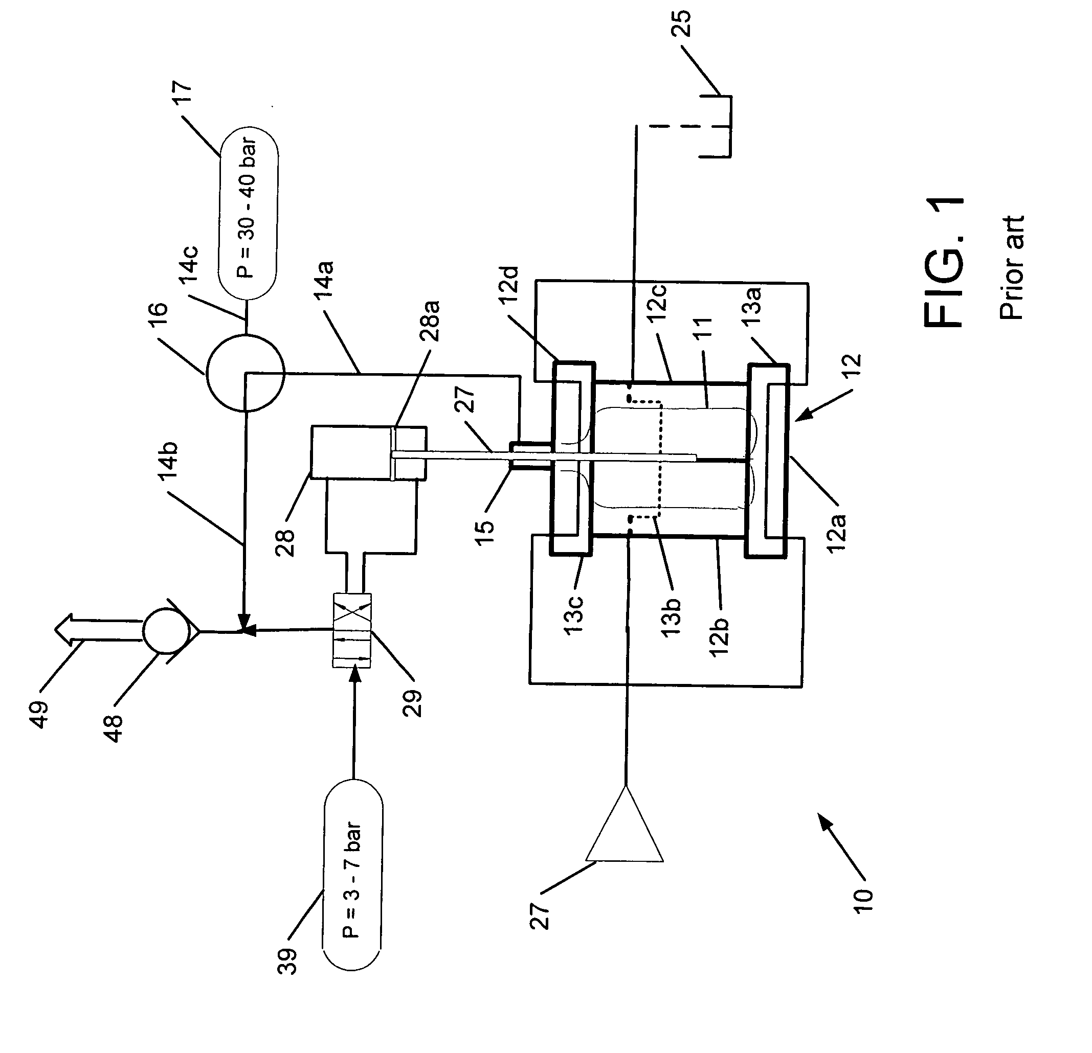
[0020]FIG. 1 shows schematically a conventional blow molding system 10, which includes a mold 12 with a mold bottom 12a, side sections 12b, 12c, and a mold neck 12d. The mold bottom 12a, side sections 12b, 12c, and mold neck 12d may be separable to facilitate un-molding a finished container 11. Although the mold 12 is shown as having two side sections 12a, 12b, it will be understood that the mold 12 may have only one side section or more than two side sections. Cooling channels 13a, 13b, 13c for...


PUM

PropertyMeasurementUnit
glass transition temperatureaaaaaaaaaa
temperatureaaaaaaaaaa

Abstract

Heat is extracted from compressed gas used in a blow-molding process by expansion cooling the exhausted gas and / or passing the exhausted gas through a vortex tube, which supplies cold gas at an exit thereof. The cold gas is then routed through cooling channels in the mold. This obviates the need for recirculating or externally chilling a coolant and saves energy.

Description

BACKGROUND OF THE INVENTION[0001]The invention relates to cooling of a mold used in a blow-molding process, and more particularly to cooling a mold or sections of a mold by recovering energy from the compressed air or gas used to operate a molding machine and to shape the containers in the mold.[0002]In a typical blow-molding process employed in the manufacture of plastic containers, such as PET (polyethylene terephthalate) bottles, the plastic starting material is heated to about 95° C., which is 20° C. above its glass transition temperature. The supplied heat softens the plastic starting material so it can be stretched to and shaped to fill the mold. Compressed air at a pressure of about 30 bar and a temperature between about 20° C. and 30° C. is blown in the interior of a preform of the container, urging the container against the walls of the mold. The container hereby takes on the shape of the mold cavity.[0003]Before the blow-molded container is removed from the mold, the mold ...

Claims


Application Information

Patent Timeline
Patent Type & Authority Applications(United States)
IPC IPC(8): B29C49/66
CPCB29C33/046B29C35/16B29C49/4823B29C2035/1658Y10S264/50B29C2049/4835B29K2067/00F25B9/04B29C2049/4833Y02P70/10B29C49/42855B29C2049/7862
Inventor LEONE, ROBERT L.
Owner NESTLE WATERS NORTH AMERICA
Why Eureka
Try Eureka