
Magnetic resonance system with components allowing upgrade capability

a technology of magnetic resonance and components, applied in the field of magnetic resonance systems, can solve the problems of inability to precisely plan the maximum expansion of the system, the inability to upgrade the capability of the system, and the inability to control the maximum expansion, etc., and achieve the effect of avoiding under-equipment or even bottlenecks, and avoiding the formation of a single componen

Active Publication Date: 2008-06-12
SIEMENS HEATHCARE GMBH
View PDF7 Cites 16 Cited by
  • Summary
  • Abstract
  • Description
  • Claims
  • Application Information

AI Technical Summary

Benefits of technology

[0010]An object of the present invention is to provide a magnetic resonance system that enables a larger and more cost-effective upgrade capability of the system.
[0017]In an embodiment, the time clock pulse of the data network fashioned as a partially isochronous or completely isochronous network is an integer multiple of the system clock pulse. The interference signals caused by the isochronous network can thereby be more easily suppressed. Additionally, no data gap between the transmitting unit and the receiving unit can arise in an isochronous network. In a further embodiment it is also possible for the clock rate of the at least partially isochronous network to precisely correspond to the system clock. For example, control commands can then be delivered to the various digital modules within one system clock and retain their validity during the following system clock pulse. Further time references in addition to the system clock are no longer necessary in this case since the system clock pulse itself can serve as a timestamp.
[0019]A timestamp for establishing a reference point in time can be transferred in addition to the system clock. The transfer of this timestamp (which can ensue, for example, in regular (periodic) intervals) can inventively be realized in different ways. The timestamp can be modulated to the system clock. In this case a suitable filter arrangement that enables the separation is provided in the receiver module. Alternatively, the timestamp can be embodied as an amplitude increase of the system clock pulse. This has the advantage that no interfering influence on the phase of the system clock pulse occurs. In order to entirely avoid such interfering influences, the synchronous network can have first synchronization lines for transfer of the system clock pulse and second synchronization lines for transfer of the timestamp. In a further alternative, the timestamp can be transferred via the data network. In this case, however, it must be ensured that the respective timestamp simultaneously reach the digital modules (possibly within a small, allowed temporal tolerance) so that the sequence workflow and the coherency conditions can be upheld. Such a realization is suitable when the data network exhibits a star topology.
[0025]In addition to the already cited components, a shim system and / or a monitoring system and / or a coil interface can furthermore be provided as components. Further components that are activated into the operation of the magnetic resonance system can be integrated without problem into the inventive control system.

Problems solved by technology

Given such centrally organized control systems, a future maximum expansion must be taken into account in the design since the capacities of the control computer are limited both spatially and in terms of capacity.
This maximum expansion, however, cannot be exactly planned for all system functionalities (thus components) at the point of time of the design since the technical developments proceed rapidly.
Under-equipages or even bottlenecks thus frequently occur in conventional control systems when the expansion possibilities are not sufficient.
This solution is technically very complicated and uneconomical and concerns only a partial aspect of one component.
Again, a complete and economical solution of the aforementioned problem is not achieved.

Method used


Image

  • Magnetic resonance system with components allowing upgrade capability
  • Magnetic resonance system with components allowing upgrade capability
  • Magnetic resonance system with components allowing upgrade capability

Examples


Embodiment Construction

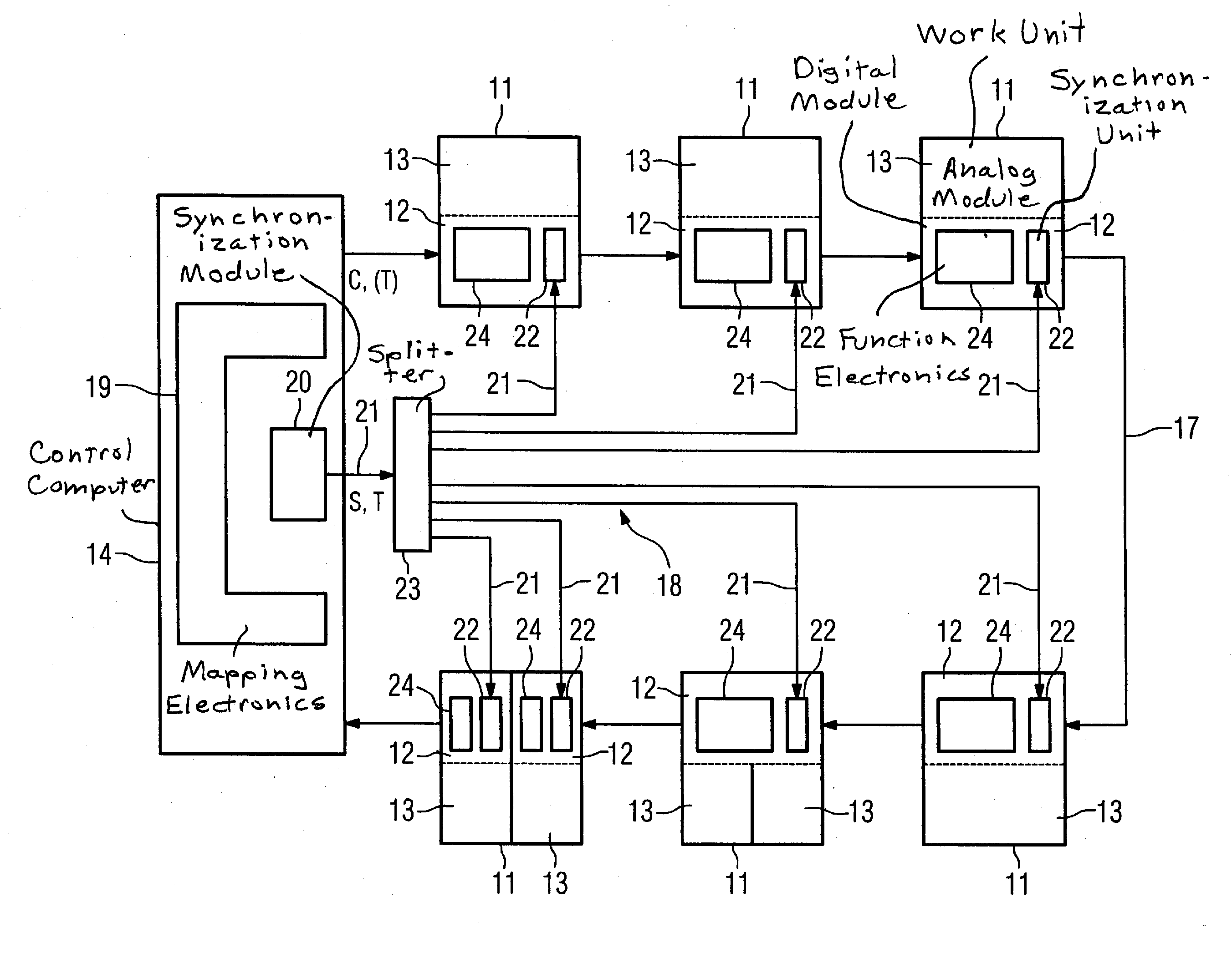
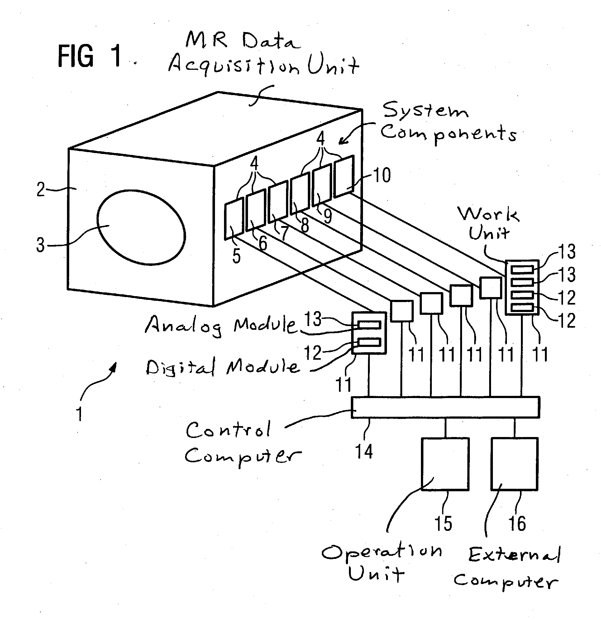
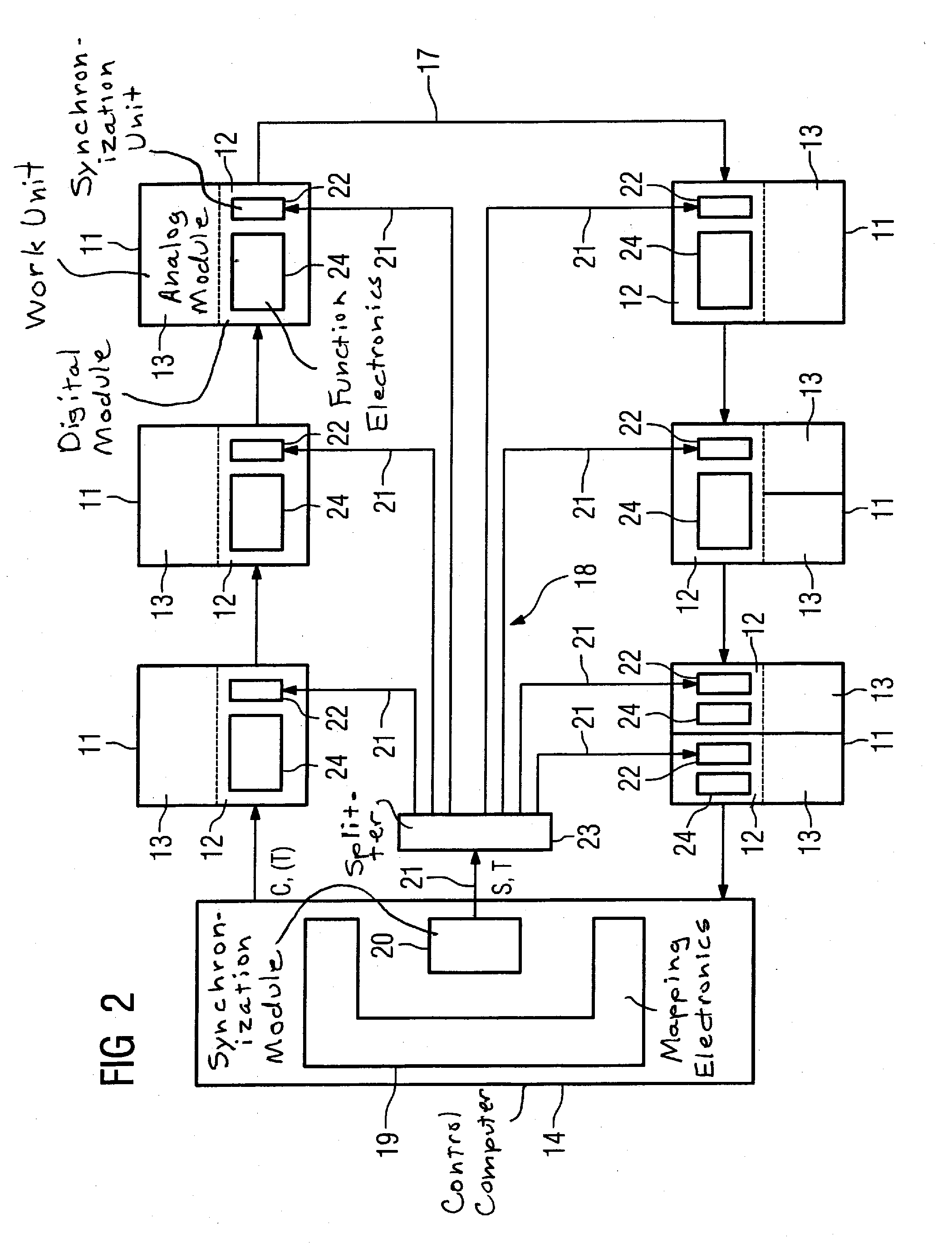
[0030]FIG. 1 schematically shows an inventive magnetic resonance system 1. It has an MR data acquisition unit 2 in which the patient receptacle 3 is also fashioned, in which patient receptacle 3 an optimally homogeneous field is generated in the isocenter. Furthermore, the magnetic resonance system 1 has a number of system components 4 that are shown only schematically. The components 4 in this case include a magnetic field generation unit 5, gradient coil 6, a radio-frequency coil arrangement 7, a shim system 8 for improvement of the homogeneity of the magnetic field, a monitoring system 9 for general monitoring tasks as well as a coil interface 10. A work unit 11 is respectively associated with the components 4 in this case. Configurations are also conceivable in which a number of components 4 are associated with a work unit 11 or a number of work units 11 are associated with a component 4. The work units 11 represent various units such as control units, supply units, measurement ...


PUM


Abstract

A magnetic resonance system has components that include a magnetic field generation unit for generation of a basic magnetic field, gradient coils for generation of a field gradient as well as a radio-frequency coil arrangement with a number of radio-frequency coils for transmission and reception of radio-frequency signals. These components can respectively be activated according to a sequence via at least one digital module and at least one analog module. The analog modules are arranged externally to a control computer controlling the digital modules. The digital modules also are arranged externally to the control computer and are associated with the analog module or modules controlled by said digital modules. A data network is provided for communication between the digital modules and the control computer and a synchronous network is provided for synchronization of the digital modules and the control computer.

Description

BACKGROUND OF THE INVENTION[0001]1. Field of the Invention[0002]The invention concerns a magnetic resonance system of the type having components, that include a magnetic field generation unit for generation of a basic magnetic field, gradient coils for generation of a field gradient as well as a radio-frequency coil arrangement with a number of radio-frequency coils for transmission and reception of radio-frequency signals; the components being respectively activated according to a sequence via at least one digital module and at least one analog module; with the analog modules being arranged external to a control computer that controls the digital modules.[0003]2. Description of the Prior Art[0004]Modern magnetic resonance systems embody a number of components that must be activated in the course of a measurement procedure (in particular a sequence) while observing fixed temporal correlations. Among these components are, for example: a magnetic field generation unit for generation o...

Claims


Application Information

Patent Timeline
IPC IPC(8): G01R33/36G01R33/28G05B15/02
CPCG05B15/02G01R33/36
Inventor BAUMGARTL, RUDIDEMHARTER, NIKOLAUSPIRKL, GEORG
Owner SIEMENS HEATHCARE GMBH
Learn More