Boost circuit and level shifter

a level shifter and boost circuit technology, applied in logic circuits, pulse automatic control, instruments, etc., can solve problems such as the level shifter may not be properly driven

Inactive Publication Date: 2008-06-12
PRINCETON TECH CORP
View PDF5 Cites 20 Cited by
  • Summary
  • Abstract
  • Description
  • Claims
  • Application Information

AI Technical Summary

Problems solved by technology

If the voltage level of the input signal applied to the level shift does not exceed a predetermined voltage level, the level shifter may be not properly driven.

Method used


Image

  • Boost circuit and level shifter
  • Boost circuit and level shifter
  • Boost circuit and level shifter

Examples


Embodiment Construction

[0012]The following description is of the best-contemplated mode of carrying out the invention. This description is made for the purpose of illustrating the general principles of the invention and should not be taken in a limiting sense. The scope of the invention is best determined by reference to the appended claims.

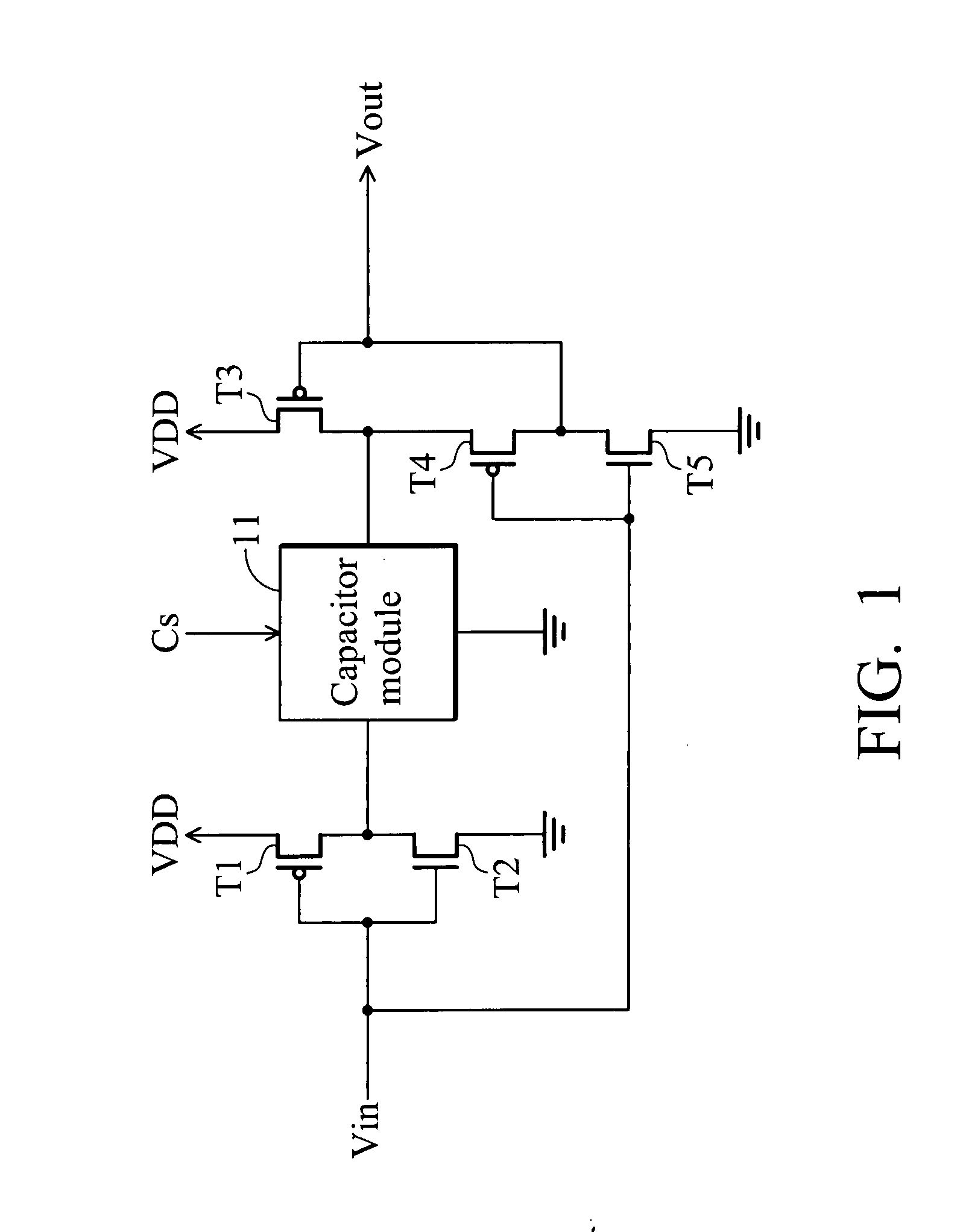
[0013]FIG. 1 is a circuit diagram of an embodiment of a boost circuit of the invention. The transistor T1 has a first source, a first gate and a first drain, wherein the first source is coupled to a voltage source VDD. The second transistor T2 has a second source, a second gate and a second drain, wherein the second drain is coupled to the first drain, the second source is grounded, and the second gate is coupled to the first gate to receive an input signal Vin. The capacitor module 11 has a first terminal and a second terminal, and is controlled by a control signal Cs to change a capacitance of the capacitor module for changing the discharge time of the capacitor modu...


PUM


Abstract

A level shifter including a first boost circuit, an inverter, a second boost circuit and a level shift circuit is disclosed. The first boost circuit receives an input signal, and a first amplification factor for the input signal is determined based on a control signal. The inverter receives the input signal to generate an inverted input signal. The second boost circuit is coupled to an output terminal of the inverter to receive the inverted input signal, and a second amplification factor for the inverted input signal is determined based on the control signal. The level shift circuit has a first input terminal and a second input terminal respectively coupled to output terminals of the first boost circuit and second boost circuit to change the voltage level of output signals from the first boost circuit and second boost circuit to a first voltage level.

Description

BACKGROUND OF THE INVENTION[0001]1. Field of the Invention[0002]The invention relates to a level shifter, and more particularly to a two-stage level shifter with a boost circuit.[0003]2. Description of the Related Art[0004]The conventional voltage pull-up circuit is typically implemented by a level shifter. The level shifter includes two input terminals respectively receiving an input signal and an inverted input signal. In a typical level shifter, the input terminal is electrically connected to the gate of a transistor. If the output current of the level shifter needs to be increased, the W / L ratio of the transistor coupled to the input terminal must be raised firstly, thus, the layout area of the level shifter will be increased. To completely turn on an NMOS transistor, the input positive voltage applied to the gate of the NMOS transistor must exceed a predetermined voltage level. If the input positive voltage applied to the gate of the NMOS transistor does not exceed the predeter...

Claims


Application Information

Patent Timeline
Patent Type & Authority Applications(United States)
IPC IPC(8): H03L5/00G05F3/02
CPCH03K19/01707H03K19/018521H03K19/01714
Inventor CHEN, YEN-WENCHOU, YEN-YNN
Owner PRINCETON TECH CORP
Why Eureka
Try Eureka