
Image Display Device, Image Display Panel, Panel Drive Device, and Method of Driving Image Display Panel

a technology of image display panel and display panel, which is applied in the direction of instruments, computing, electric digital data processing, etc., can solve the problems of wasteful power consumption, large area penalty, and large pre-charge circuit scale, and achieve the effect of shortening the time of supply of pixel data, increasing the load capacitance of signal lines, and sufficient pre-charging of signal lines

Inactive Publication Date: 2008-06-12
JAPAN DISPLAY INC
View PDF5 Cites 14 Cited by
  • Summary
  • Abstract
  • Description
  • Claims
  • Application Information

AI Technical Summary

Benefits of technology

[0025]Preferably, the precharging control circuit (40) changes the time duration or number of the precharge pulses (62R, 62G, 62B) to increase the time of the precharge the shorter the time duration of the permission pulse (63R, 63G, 63B) for the supply of data and the later the display of the color in the line display period (time duration of the pulse 60).

Problems solved by technology

Further, a second problem to be solved by the present invention is that a high precharging capability is required for package precharging for each of the three primary colors or each line, the scale of the precharge circuit increases and the area penalty becomes large, and wasteful power consumption occurs.

Method used


Image

  • Image Display Device, Image Display Panel, Panel Drive Device, and Method of Driving Image Display Panel
  • Image Display Device, Image Display Panel, Panel Drive Device, and Method of Driving Image Display Panel
  • Image Display Device, Image Display Panel, Panel Drive Device, and Method of Driving Image Display Panel

Examples


Embodiment Construction

[0043]The present invention can be preferably utilized in an image display device of beam scanning type like CRT other than the image display device of fixed pixels for example LCD (Liquid Crystal Display), DMD (Digital Micro-mirror Device) or organic EL element. Further, the present invention can be preferably utilized for also an image display device having a built-in precharge circuit or a drive device of the image display panel. Further, the present invention can be applied to both of a line sequential driveline sequential drive and point sequential drive.

[0044]Here, an embodiment of the present invention will be explained by taking as an example a liquid crystal display device of a so-called multiplex system (also referred to as a “selector system”), one type of line sequential drive, decreasing the number of interconnects which are horizontally driven at one time by multiplex control. Here, the term “line sequence” means a “horizontal driving system for displaying color once a...


PUM

PropertyMeasurementUnit
timeaaaaaaaaaa
coloraaaaaaaaaa
colorsaaaaaaaaaa

Abstract

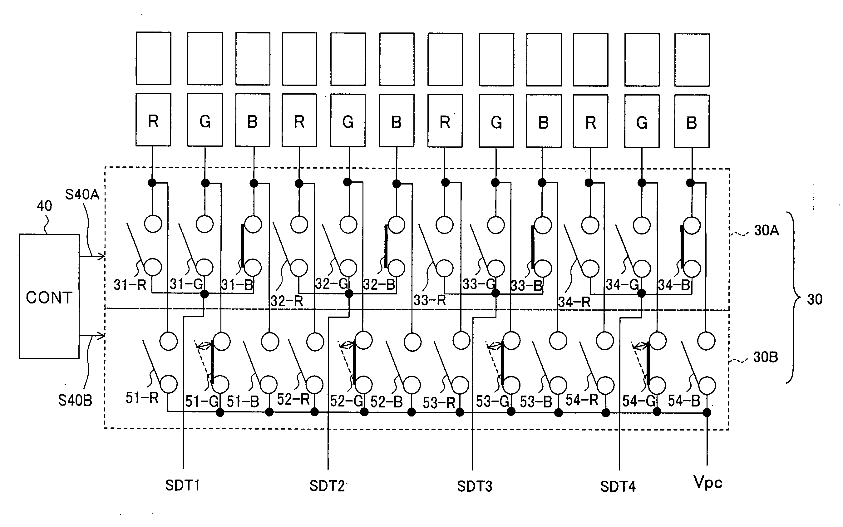
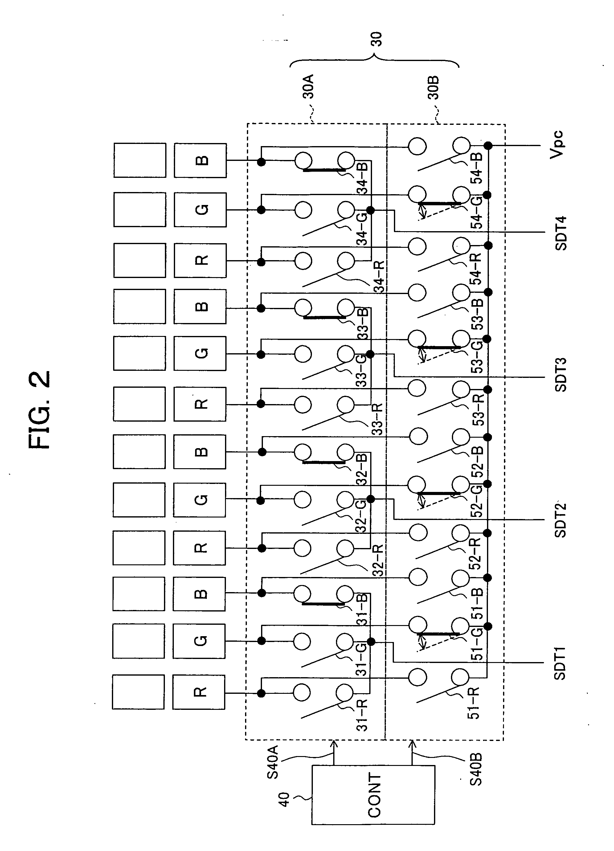
In the present invention, during a 1H period excluding a blanking period (1HB) constituting a line display period, pixel data pulses of RGB (61B to 61R) are successively supplied for each color to corresponding signal lines for color display of one pixel line. A control circuit (40) of select switches connected to the signal lines (6-1 to 6-n) supplies permission pulses (63B to 63R) for supply of data to signal lines when displaying one color among RGB to select switches (TMG), and turns on the select switch (TMG) of the signal line corresponding to another color to be displayed later in the same line display period during the period of this application by a precharge pulse (62G or 62R) having a time duration shorter than the supply time of the pixel data of the other color (T2 or T3) to previously precharge the signal line of the other color to the predetermined potential. Due to this, sufficient precharging of a signal line which became difficult due to an increase of a load capacitance of the signal line due to higher definition of the image display device and increase in speed of a drive clock thereof can be achieved.

Description

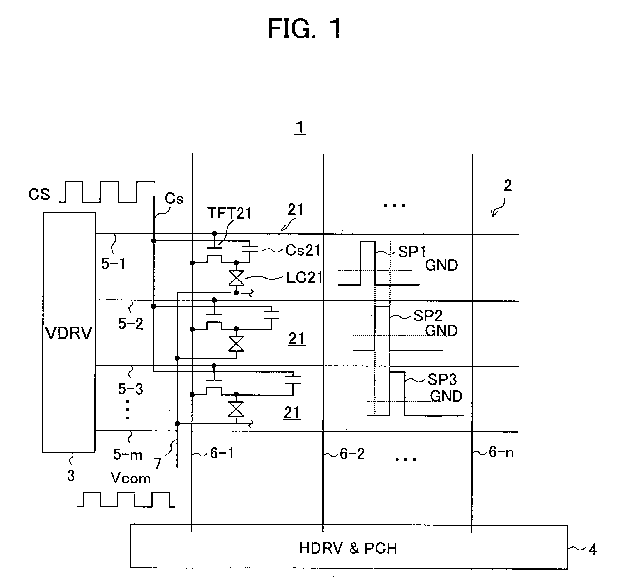
TECHNICAL FIELD[0001]The present invention relates to an image display device for precharging a signal line with a predetermined potential in advance when successively supplying pixel data of three primary colors to the related signal line during a period excluding a blanking period of one horizontal scanning period, that is, a line display period, an image display panel having a precharge function, and a drive device and a method of driving an image display device.BACKGROUND ART[0002]A for example liquid crystal display or other image device display having fixed pixels, as is well known, has an effective pixel area in which a plurality of pixel circuits (hereinafter simply referred to as “pixels”) are arrayed in a matrix and in which three primary colors are assigned to the pixels in a predetermined array.[0003]Each pixel of the liquid crystal display, while not particularly shown, is comprised of a pixel select element constituted by a thin film transistor (TFT), a liquid crystal ...

Claims


Application Information

Patent Timeline
Patent Type & Authority Applications(United States)
IPC IPC(8): G06F3/038G09G3/20G02F1/133G09G3/36
CPCG09G3/2011G09G3/2074G09G3/3607G09G3/3648G09G2320/0223G09G3/3688G09G2310/0251G09G2310/0297G09G3/3677G09G3/36
Inventor ITAKURA, NAOYUKIICHIKAWA, HIROAKIMAEKAWA, TOSHIKAZU
Owner JAPAN DISPLAY INC
Learn More