Geometric Correction Method in Multi-Projection System

a multi-projection system and geometric correction technology, applied in the field of multi-projection system, can solve the problems of difficult to find correspondences between the detected feature points in the captured images and the plurality of feature points in the original test pattern images, and achieve the effect of simple and accurate manual operations, short time-consuming, and simple and convenient manual operations

Inactive Publication Date: 2008-06-12
OLYMPUS CORP
View PDF2 Cites 73 Cited by
  • Summary
  • Abstract
  • Description
  • Claims
  • Application Information

AI Technical Summary

Benefits of technology

[0041]According to the invention, it is possible to effect setting of detection areas of feature points as an initial setting for positioning in a multi-projection system by simplified and convenient manual operations by a user so that the geometric correction can be simply and accurately carried out in short a time without choosing wrong order of the feature points even if a screen having a complicated shape is used or projected images by projectors or captured images by capturing means have been remarkably tilted or rotated, thereby enabling the maintenance efficiency to be significantly improved.

Problems solved by technology

With such a method for calculating the image correction data, however, when the shape of the screen is complicated or the arrangement of the projectors is complicated and the orientations of the projected images have been remarkably rotated, it may become difficult to find correspondences between the detected feature points in the captured images and the plurality of feature points in the original test pattern images.

Method used


Image

  • Geometric Correction Method in Multi-Projection System
  • Geometric Correction Method in Multi-Projection System
  • Geometric Correction Method in Multi-Projection System

Examples


first embodiment

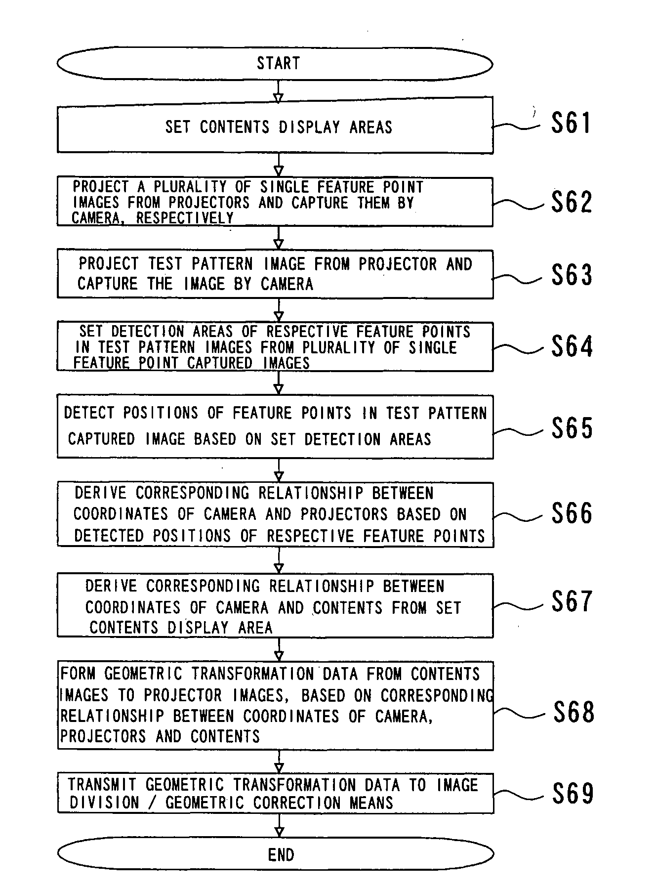
[0071]FIGS. 1 to 7 illustrate the configuration of the first embodiment according to the invention.

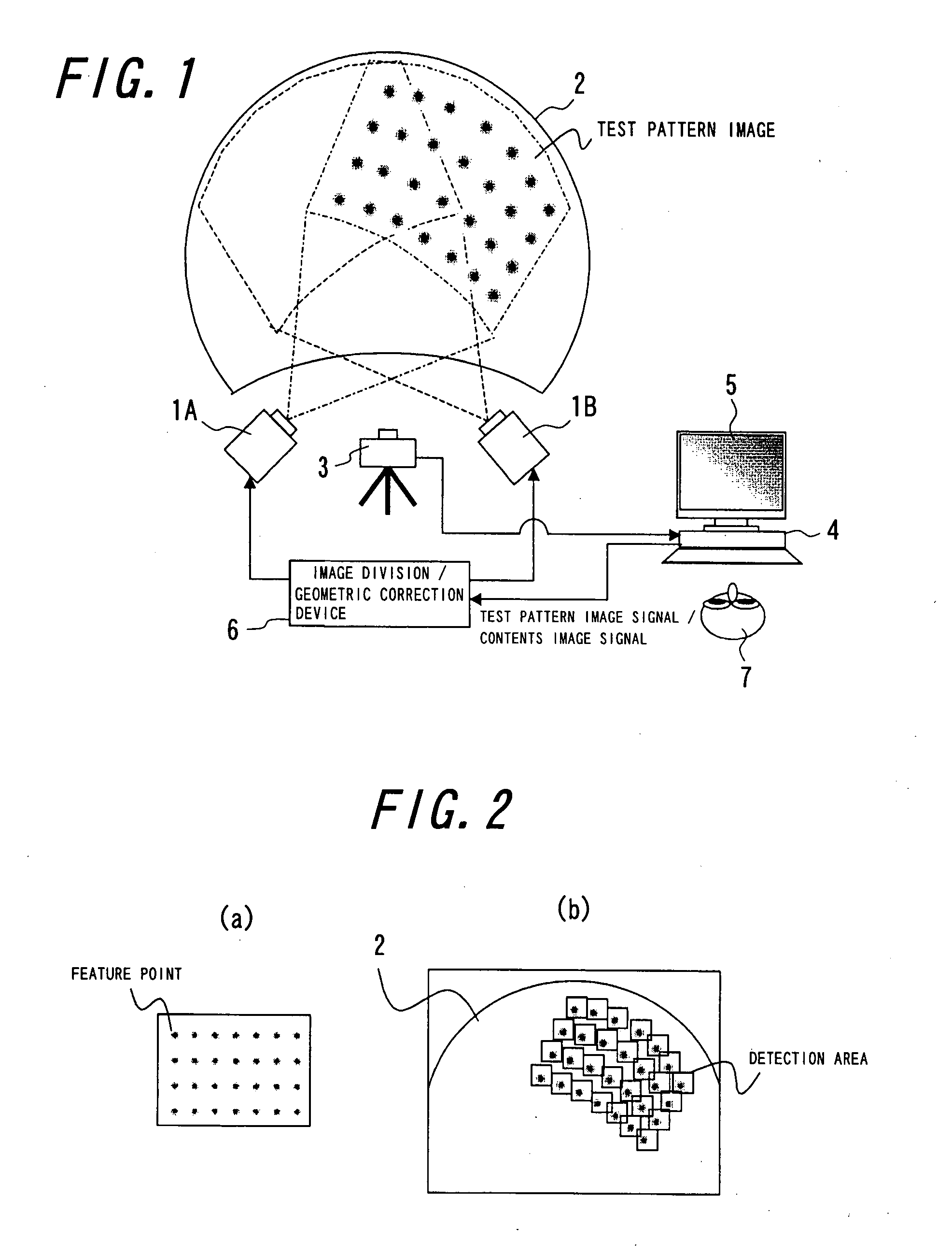
[0072]A multi-projection system according to the present embodiment, the entirety of which is illustrated in FIG. 1, comprises a plurality of projectors (projectors 1A and 1B in this case), a dome-shaped screen 2, a digital camera 3, a personal computer (PC) 4, a monitor 5, and an image division / geometric correction device 6. Pictorial images are projected onto the screen 2 by means of the projectors 1A and 1B so that the projected images are combined with one another to display one large pictorial image on the screen 2.

[0073]In such a multi-projection system, if the pictorial images are simply projected from the projectors 1A and 1B, the respective projected images may not be snugly combined with one another due to color characteristics of the respective projectors, deviations in the projecting positions, and distortions in the images projected onto the screen 2.

[0074]In the present e...

second embodiment

[0114]FIG. 11(a) to (d) illustrate the configuration of the second embodiment according to the invention.

[0115]In the second embodiment, the test pattern images produced in the test pattern image generating section are images having marks (numbers) added to the proximities of the feature points as shown in FIG. 11(a), instead of the test pattern images in the first embodiment as shown in FIG. 2(a). The other constructions and operations are similar to those in the first embodiment and hence, the explanation is omitted.

[0116]By using the images having marks (numbers) added to the proximities of the feature points as test pattern images in this manner, the displayed images can be selected in a corresponding order to enable the alignment or positioning without failures. This is because the points in the test pattern captured images to be designated have the numbers as markers as shown in FIG. 11(b), even if the individual projected images by the projectors are significantly rotated or ...

third embodiment

[0118]FIG. 12 is a block diagram illustrating the constitution of the geometric correction means according to the third embodiment of the invention.

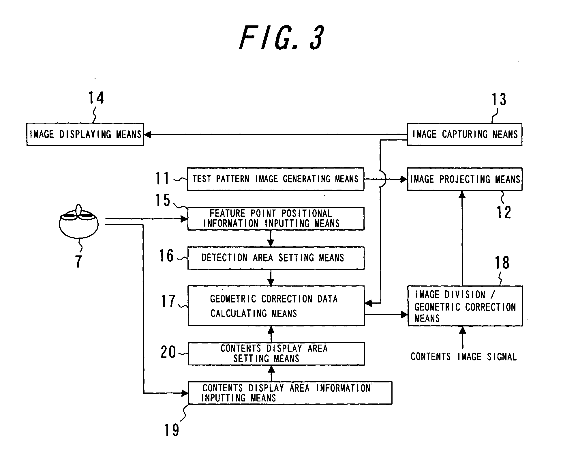
[0119]In the present embodiment, network control means 28a and network control means 28b are provided in addition to the construction of the geometric correction means shown in the first embodiment (refer to FIG. 3). In more detail, the network control means 28a is connected through a network 29 to the network control means 28b positioned in a remote place, and transmits screen captured images and test pattern captured images captured by the image capturing means 13 to the network control means 28b through the network 29. The network control means 28a further receives approximate position information of the feature points and contents display area information transmitted through the network 29 from the network control means 28b, and outputs these information to the detection area setting means 16 and the contents display area setting mea...


PUM


Abstract

A geometrical correcting method allowing geometrical correction to be performed simply, accurately and in short a time, even in a multi-projection system including a screen of complex shape and projectors complexly arranged, for significantly improving the maintenance efficiency. Test pattern images having feature points are projected by respective projectors, and captured and displayed on a monitor, approximate positions of the feature points are designated and input while referring to the displayed test pattern captured image, and the accurate positions of the feature points in the test pattern images are detected according to the approximate position information. An image correction data for aligning the images projected by the projectors is calculated from the detected positions based on the feature points, the coordinate information of the feature points in a predetermined test pattern image, and the coordinate position relationship between a separately predetermined contents image and the test pattern captured image.

Description

TECHNICAL FIELD[0001]This invention relates to a multi-projection system projecting pictorial images in an overlapping relationship on a screen by using a plurality of projectors, and in particular to a geometric correction method for automatically correcting positional deviations between the respective projectors and distortions in the images by detecting such deviations and distortions by a camera.BACKGROUND ART[0002]Multi-projection systems came to be widely used in recent years, for displaying combined images on a screen by a plurality of projectors in order to construct large-sized and high definition displays for showrooms in museums, exhibitions and the like, or for virtual reality (VR) systems and the like for use in simulation of theaters, automobiles, buildings, urban landscapes and the like.[0003]In such multi-projection systems, it is important to adjust or correct positional deviations of images and color shifting for finely combining the images on a screen. A method fo...

Claims


Application Information

Patent Timeline
Patent Type & Authority Applications(United States)
IPC IPC(8): G06F3/14
CPCG03B21/14G03B21/56H04N9/3194H04N9/3185G03B37/04
Inventor AJITO, TAKEYUKIYAMAGUCHI, KAZUO
Owner OLYMPUS CORP
Why Eureka
Try Eureka