
Method and system for level detector calibration for accurate transmit power control

a technology of transmit power control and level detector, applied in power management, transmitter monitoring, wireless communication, etc., can solve the problems of reducing the output power of pa, fcc or standard limit is never exceeded, and impose limitations on the performance of the integrated pa circuitry

Active Publication Date: 2008-06-12
AVAGO TECH INT SALES PTE LTD
View PDF6 Cites 16 Cited by
  • Summary
  • Abstract
  • Description
  • Claims
  • Application Information

AI Technical Summary

Problems solved by technology

An inaccuracy in the level detector may cause the system to be designed with decreased output power of the PA, such that the FCC or standard's limit is never exceeded.
Whereas the pressing need to increase the integration of functions performed within a single IC, and attendant increase in the number of semiconductor devices, may push semiconductor fabrication technologies toward increasingly shrinking semiconductor device geometries, these very semiconductor fabrication technologies may impose limitations on the performance of the integrated PA circuitry.
For example, utilizing a 65 nm CMOS process may restrict the range of input power levels for which the PA provides linear output power level amplification.

Method used


Image

  • Method and system for level detector calibration for accurate transmit power control
  • Method and system for level detector calibration for accurate transmit power control
  • Method and system for level detector calibration for accurate transmit power control

Examples


Embodiment Construction

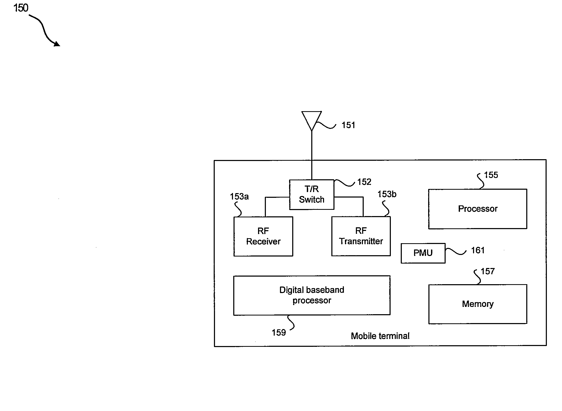
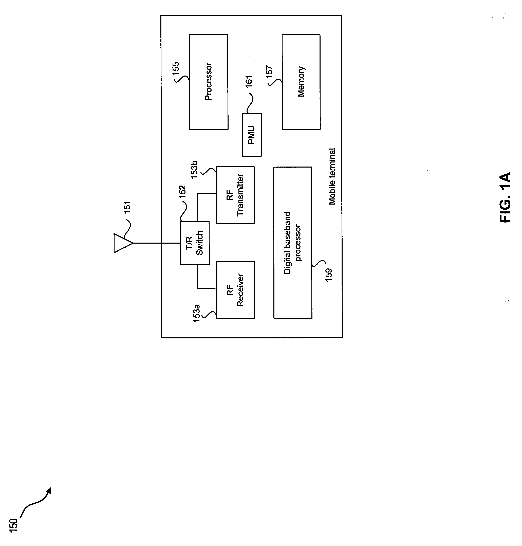
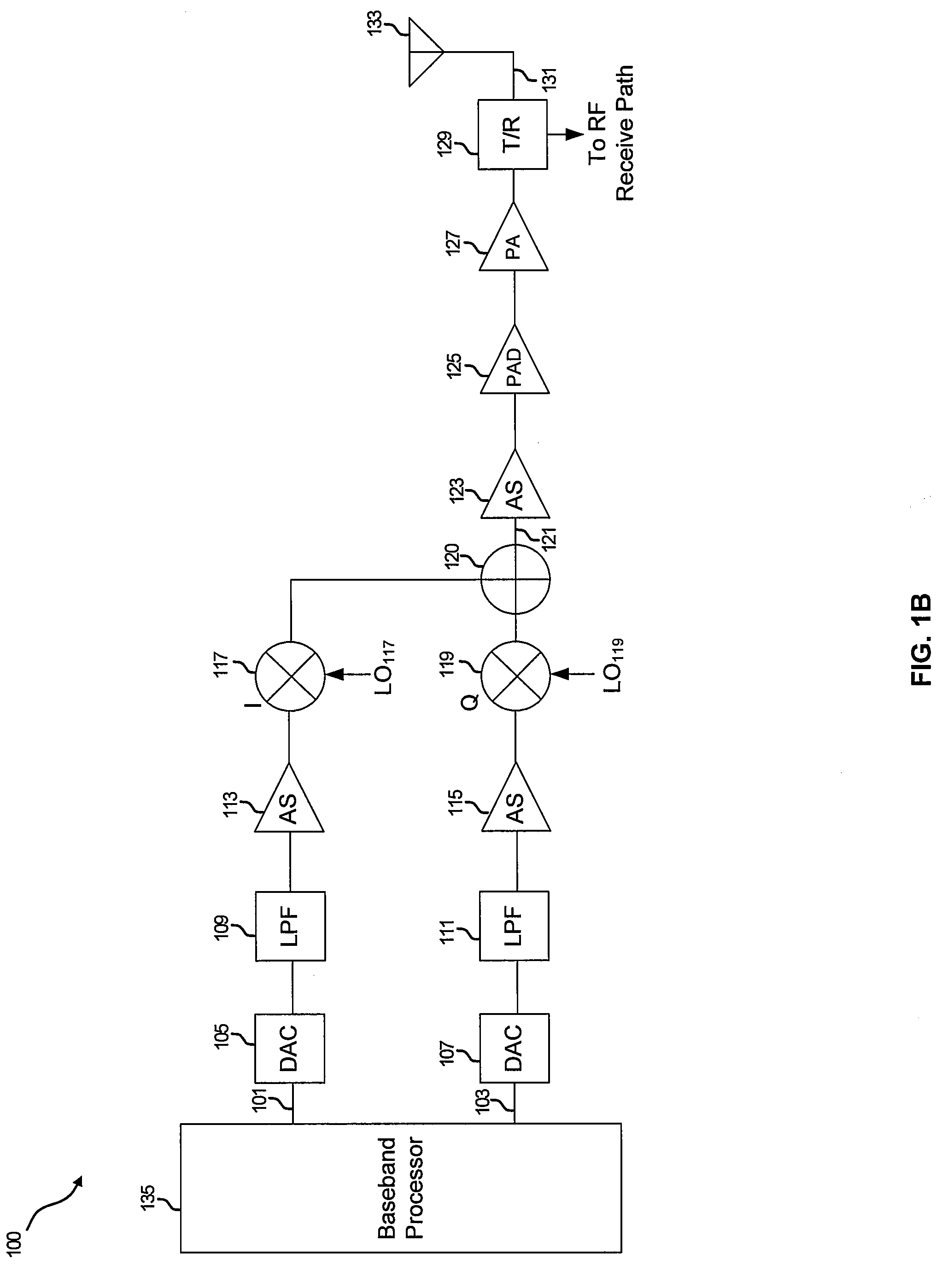
[0021]Certain aspects of the invention may be found in a method and system for level detector calibration. Aspects of the invention may comprise calibrating a level detector integrated on-chip to eliminate an associated zero input offset voltage utilizing a replica bias circuit with no input ac voltage at either the level detector or the replica bias circuit. The offset voltages of the level detector and the replica bias circuit may be combined to eliminate the associated zero input offset voltage of the level detector. The output signal may be generated by a difference of an output signal from the level detector and an output signal from the replica bias circuit. The level detector and the replica bias circuit may be biased utilizing a similar bias voltage. A plurality of known input voltages may be utilized to generate a corresponding plurality of output voltages of the level detector. The known reference input voltages may be generated by clipping an input VCO signal and applying...


PUM


Abstract

Methods and systems for level detector calibration are disclosed and may comprise calibrating a level detector integrated on-chip to eliminate an associated zero input offset voltage utilizing a replica bias circuit with no input ac voltage at the level detector or the replica bias circuit. The offset voltages of the level detector and the replica bias circuit may be combined to eliminate the associated zero input offset voltage of the level detector. The output signal may be generated by a difference of output signals from the level detector and the replica bias circuit. The level detector and the replica bias circuit may be biased utilizing a similar bias voltage. A plurality of known input voltages may be utilized to generate a corresponding plurality of output voltages of the level detector, generating a corrected transfer function that may be used to accurately set a transmitter power level.

Description

CROSS-REFERENCE TO RELATED APPLICATIONS / INCORPORATION BY REFERENCE[0001]This application makes reference to, claims priority to, and claims the benefit of U.S. Provisional Application Ser. No. 60 / 868,818, filed on Dec. 6, 2006.[0002]The above stated application is hereby incorporated herein by reference in its entirety.FEDERALLY SPONSORED RESEARCH OR DEVELOPMENT[0003][Not Applicable][MICROFICHE / COPYRIGHT REFERENCE][0004][Not Applicable]FIELD OF THE INVENTION[0005]Certain embodiments of the invention relate to controlling of circuits utilized in communication devices. More specifically, certain embodiments of the invention relate to a method and system for level detector calibration.BACKGROUND OF THE INVENTION[0006]A power amplification circuit in a wireless system is typically a large signal device. In wireless local area network (WLAN) systems, the power amplifier (PA) circuit may transmit output signals at average power levels in the range of 10 dBm to 20 dBm, and peak power level...

Claims


Application Information

Patent Timeline
Patent Type & Authority Applications(United States)
IPC IPC(8): H01Q11/12
CPCH03F3/45183H03G3/3042H04B17/13H04W52/52H04B2001/0416
Inventor BEHZAD, ARYA
Owner AVAGO TECH INT SALES PTE LTD
Learn More