Ultrasonic Probe and Ultrasonic Diagnosis Apparatus

Inactive Publication Date: 2008-06-12
HITACHI LTD
View PDF8 Cites 23 Cited by
  • Summary
  • Abstract
  • Description
  • Claims
  • Application Information

AI Technical Summary

Benefits of technology

[0021]The second attenuation section is desirably formed having a void, and the void may be filled in with a sound absorbing material. By such configuration, effect for attenuating noise that appears on an ultrasound image can be further improved.
[0022]As mentioned above,

Problems solved by technology

However, there are cases that the incoming ultrasonic waves from the transducer to the backside return to the transducer side by reflecting at the backside, especially at the bonded surface of the backin

Method used


Image

  • Ultrasonic Probe and Ultrasonic Diagnosis Apparatus
  • Ultrasonic Probe and Ultrasonic Diagnosis Apparatus
  • Ultrasonic Probe and Ultrasonic Diagnosis Apparatus

Examples


first embodiment

THE FIRST EMBODIMENT

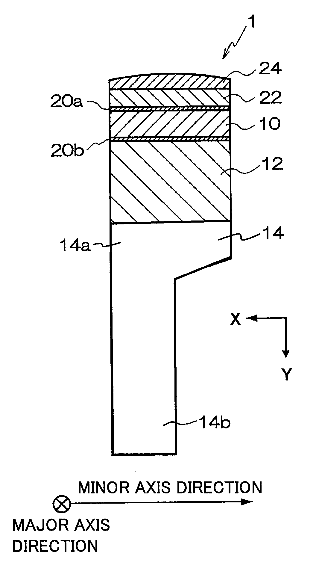
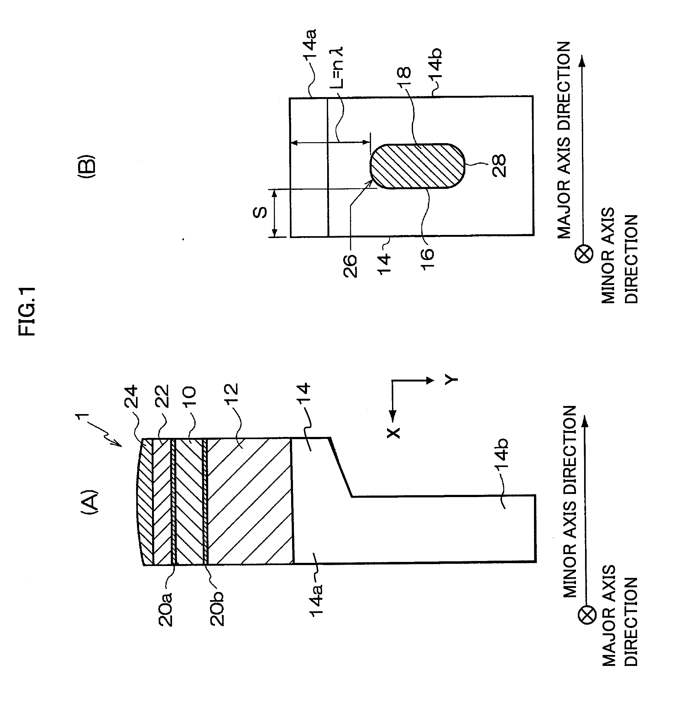
[0023]The first embodiment of the ultrasonic probe to which the present invention is applied will be described referring to the diagrams. FIG. 1A is a diagram showing a cross section in axis direction of the ultrasonic probe of the present embodiment, viewing from major axis direction. FIG. 1B is a diagram showing a heat-dissipating block of FIG. 1A viewing from major axis direction (direction of arrow X shown in the diagram).

[0024]As shown in FIG. 1A and FIG. 1B, ultrasonic probe 1 to use for imaging an ultrasound image of the object comprises transducer 10 for transmitting / receiving ultrasonic waves between the object and the backside section imposed on the backside of the transducer. The backside section has backing material 12 as the backing layer (the first attenuation section) imposed on the backside of transducer 10 and heat-dissipating block 14 as the heat-dissipating section laminated on the backside of backing material 12. Ultrasonic probe 1 is stored i...

second embodiment

[0054]A second embodiment of the ultrasonic probe to which the present invention is applied will be described referring to FIG. 5. The present embodiment is different, in the point of using a triple layered heat-dissipating section, from the first embodiment using the heat-dissipating block in which the void is formed. Therefore, points of difference will be mainly described, by using the same symbols for the places relatively corresponding to the first embodiment.

[0055]FIG. 5 is a diagram showing a cross section in axis direction of ultrasonic probe of the present embodiment 1b, viewing from minor axis direction. As shown in FIG. 5, in ultrasonic probe 1b, a triple layered heat-dissipating section is disposed in the backside of backing material 12. The heat-dissipating section has heat-dissipating member 51 as the first heat-dissipating layer disposed on the backside of backing material 12, sound absorbing material 52 as the sound-absorbing layer laminated on the backside of heat-d...

third embodiment

THE THIRD EMBODIMENT

[0060]The third embodiment of the ultrasonic probe to which the present invention is applied will be described referring to FIG. 6. The present embodiment has the position and size of the void that are different from the first embodiment. Therefore, points of difference will be mainly described, by using the same symbols for the places relatively corresponding to the first embodiment.

[0061]FIG. 6 is a diagram showing a cross section in axis direction of ultrasonic probe 1c of the present invention, viewing from major axis direction. As shown in FIG. 6, in ultrasonic probe 1c, void 60 is formed in bonded section 14a of heat-dissipating block 14. Void 60 passes through bonded section 14a in major axis direction, and is zoned by two flat surfaces parallel to the backside of backing material 12 and a rounded surface connecting the respective flat surfaces. Void 60 also may be formed in a part of major axis direction without passing through in major axis direction. Di...


PUM


Abstract

An ultrasonic probe suitable for reducing reflected waves returning from a rear surface part to a transducer side, and an ultrasonic diagnostic apparatus. Ultrasonic probe 1 comprises transducer 10 transmitting and receiving ultrasonic waves to and from a subject, a backing material 12 disposed on the rear side of the transducer 10, and heat dissipating block 14 stacked on the backside of the backing material 12.
At least one of the backing material 12 and heat-dissipating block 14 comprises void 16 therein. A sound absorbing material 18 is desirably filled in void 16.

Description

TECHNICAL FIELD [0001]The present invention relates to an ultrasonic probe in which transducers are arranged for transmitting and receiving ultrasonic waves between an object to be examined, and an ultrasonic diagnostic apparatus for constructing an ultrasonic image as a diagnostic image of the object.BACKGROUND ART[0002]An ultrasonic diagnostic apparatus is for providing driving signals to an ultrasonic probe, and for reconstructing an ultrasonic image based on the receiving signal outputted from the ultrasonic probe. An ultrasonic probe is for converting the driving signals into ultrasonic waves and transmitting them to the object, and has transducers arranged therein which are for receiving the reflected echo signals generated from the object and converting them into the receiving signals.[0003]In an ultrasonic probe, upon transmitting ultrasonic waves from the transducers to the object, ultrasonic waves are effused also to the backside of the probe. Given this factor, a backside...

Claims


Application Information

Patent Timeline
IPC IPC(8): A61B8/14
CPCA61B8/00G01S7/52017B06B1/0618G01S7/52079
Inventor HU, ZHIQIANG
Owner HITACHI LTD
Why Eureka
Try Eureka