
Hand-held cutter with automatic blade changer

a technology of automatic blade change and hand-held cutter, which is applied in the direction of manufacturing tools, portable power-driven tools, transportation and packaging, etc., can solve the problems that the method of bending, breaking and continuous use of blades cannot be applied to industrial cutters, and the user's fingers may easily be injured, etc., to achieve the effect of effective protection of personal safety, simple construction and convenient operation

Inactive Publication Date: 2008-06-19
COSIMEX H K
View PDF28 Cites 15 Cited by
  • Summary
  • Abstract
  • Description
  • Claims
  • Application Information

AI Technical Summary

Benefits of technology

[0005]In view of the aforesaid disadvantages now present in the prior art, the object of the present invention is to provide a hand-held cutter with automatic blade changer which is simple in construction and convenient to use, and allows the users to change and dispose of the blades without touching the blades, thereby effectively protecting personal safety.

Problems solved by technology

However, the process of bending, breaking and changing must be operated by hand, and if sufficient care is not taken, the user's fingers may easily be injured.
Further, during the process of bending and breaking, the blunt end of the blade may spring out causing injuries.
Improper disposal of the discarded blunt end of the blade may also easily cause accidents.
These are particularly dangerous to school children.
Nevertheless, the method of bending, breaking and continuous use of the blades cannot be applied to industrial cutters.
Therefore, changing of the blades must be accomplished by hand piece by piece while the safety means makes it difficult to change the blades.
However, this increases the size and weight of the cutters, which is not favorable to the cutters' basic characteristics of being hand-held tools.
Furthermore, most of the changing of the blades is operated by hand and that is not safe enough.
Although the prior art also provides cutters capable of automatic changing of blades, their construction is more complicated, and the cutters are composed of a plurality of parts and components so the costs of production are higher.
The cutters are larger in size and heavier in weight, and are not convenient to use.
Disposal of the blunted blades is still required to be operated by hand and it is not sufficiently safe.

Method used


Image

  • Hand-held cutter with automatic blade changer
  • Hand-held cutter with automatic blade changer
  • Hand-held cutter with automatic blade changer

Examples


Embodiment Construction

[0049]The preferred embodiments of the present invention are further described in detail with the following embodiment and the accompanying drawings.

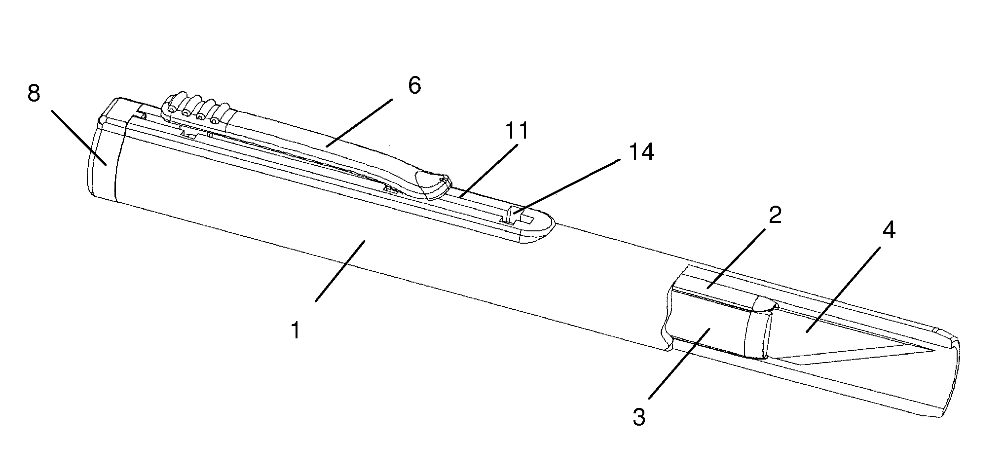
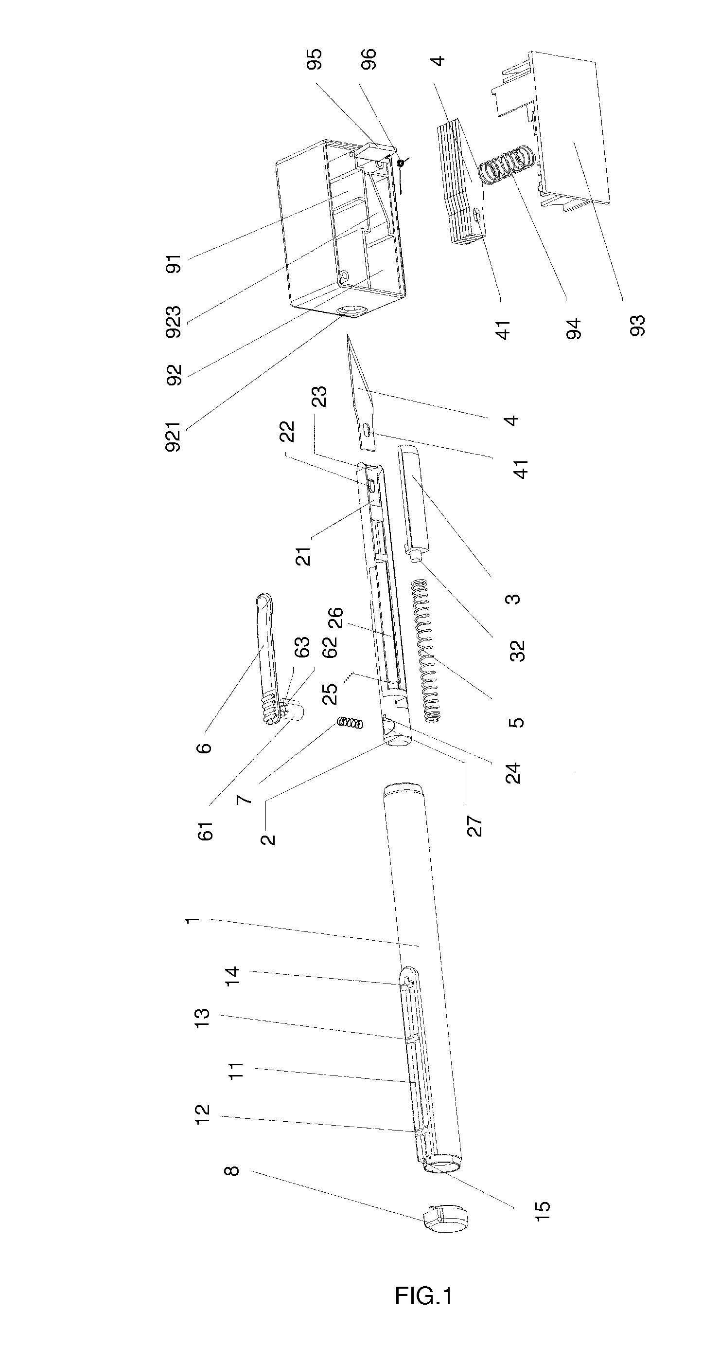
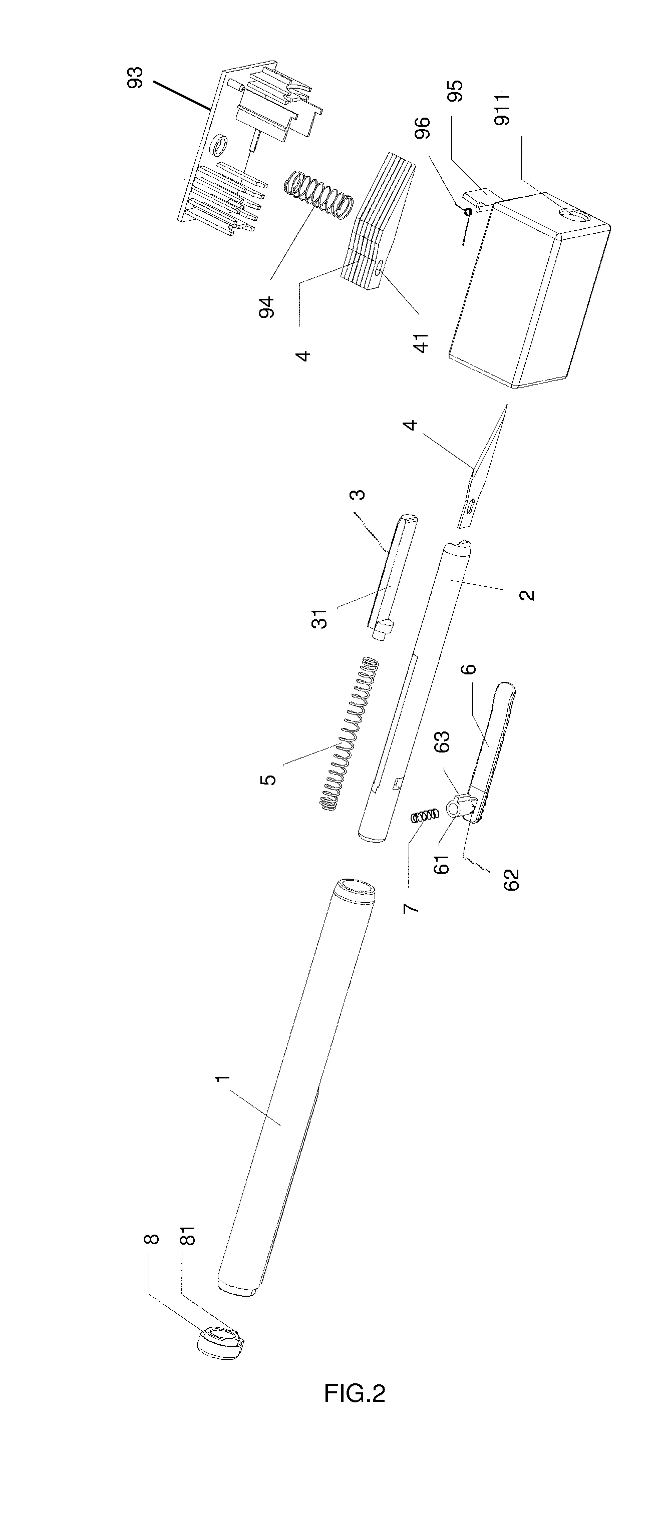
[0050]FIGS. 1 to 10 illustrate the construction of an embodiment of the present invention. As shown in FIGS. 1 and 2, the embodiment comprises a casing which is composed of an outer casing 1, a fixed blade holder 2 and a retractable blade holder 3, blades 4, a reset spring 5, a pushbutton 6, a spring 7, a plug 8 and a blade changer 9. Blades 4 are short blades each with an aperture 41 and are for industrial hand-held cutters, and in this embodiment, blades of number 11 are used, while in other embodiments, other sizes of blades may be used. In this embodiment, the head of the fixed blade holder 2 is disposed with a plane surface 21, and a projection 22 is disposed on the plane surface 21, and by inserting the projection 22 into the aperture 41 of one of the blades 4, the blade 4 can be fixed securely on the head of the fixed blade holde...


PUM


Abstract

A hand-held cutter with automatic blade changer which comprises a casing, short blades each with an aperture, a pushbutton and a plug, and the casing is composed of an outer casing, a fixed blade holder and a retractable blade holder; and it further comprises a blade changer which is divided into a blade unloading chamber and a blade loading chamber. The present invention has the advantages of being simple in construction and convenient to use, and allowing the users to change and dispose of the blades without touching them, thereby effectively protecting personal safety.

Description

BACKGROUND OF THE INVENTION[0001]The present invention relates to a hand-held cutting tool and more particularly pertains to a hand-held cutter with automatic blade changer.[0002]Hand-held cutters are generally classified into two categories, namely, for stationery purposes and for industrial purposes. Hand-held cutters for stationery purposes are office or student supplies for cutting sheets of paper. The blade for such a cutter is in the form of a strip. On the surface of the blade, a plurality of evenly spaced straight grooves is cut so that after the foremost pointed end of the blade has become blunt, the blunt pointed end of the blade can be bent and broken at the foremost groove, thereby allowing continuous use of the next sharp pointed end of the blade. When the whole strip of the blade is used up, it can be replaced by a new strip. However, the process of bending, breaking and changing must be operated by hand, and if sufficient care is not taken, the user's fingers may easi...

Claims


Application Information

Patent Timeline
IPC IPC(8): B26B3/06
CPCB26B5/003B26B5/001
Inventor CO, VICTOR
Owner COSIMEX H K
Learn More