Vortex flowmeter with temperature compensation

Active Publication Date: 2008-06-19
MICRO MOTION INC
View PDF13 Cites 37 Cited by
  • Summary
  • Abstract
  • Description
  • Claims
  • Application Information

AI Technical Summary

Problems solved by technology

A second type of vortex flowmeter does not include pressure and temperature sensors and is not capable of calculating mass flow.
Manufacture of two

Method used


Image

  • Vortex flowmeter with temperature compensation
  • Vortex flowmeter with temperature compensation
  • Vortex flowmeter with temperature compensation

Examples


Embodiment Construction

[0016]As illustrated and as used in this application, the term “thermocouple” means a circuit comprising two thermal junctions that are electrically connected together by a first conductor comprising a first material. As used in this application, the term “thermal junction” means a contact between the first material and second material.

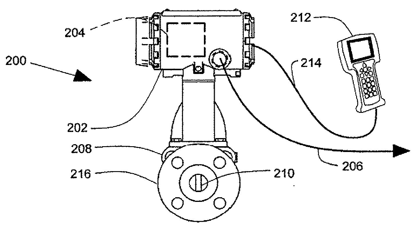
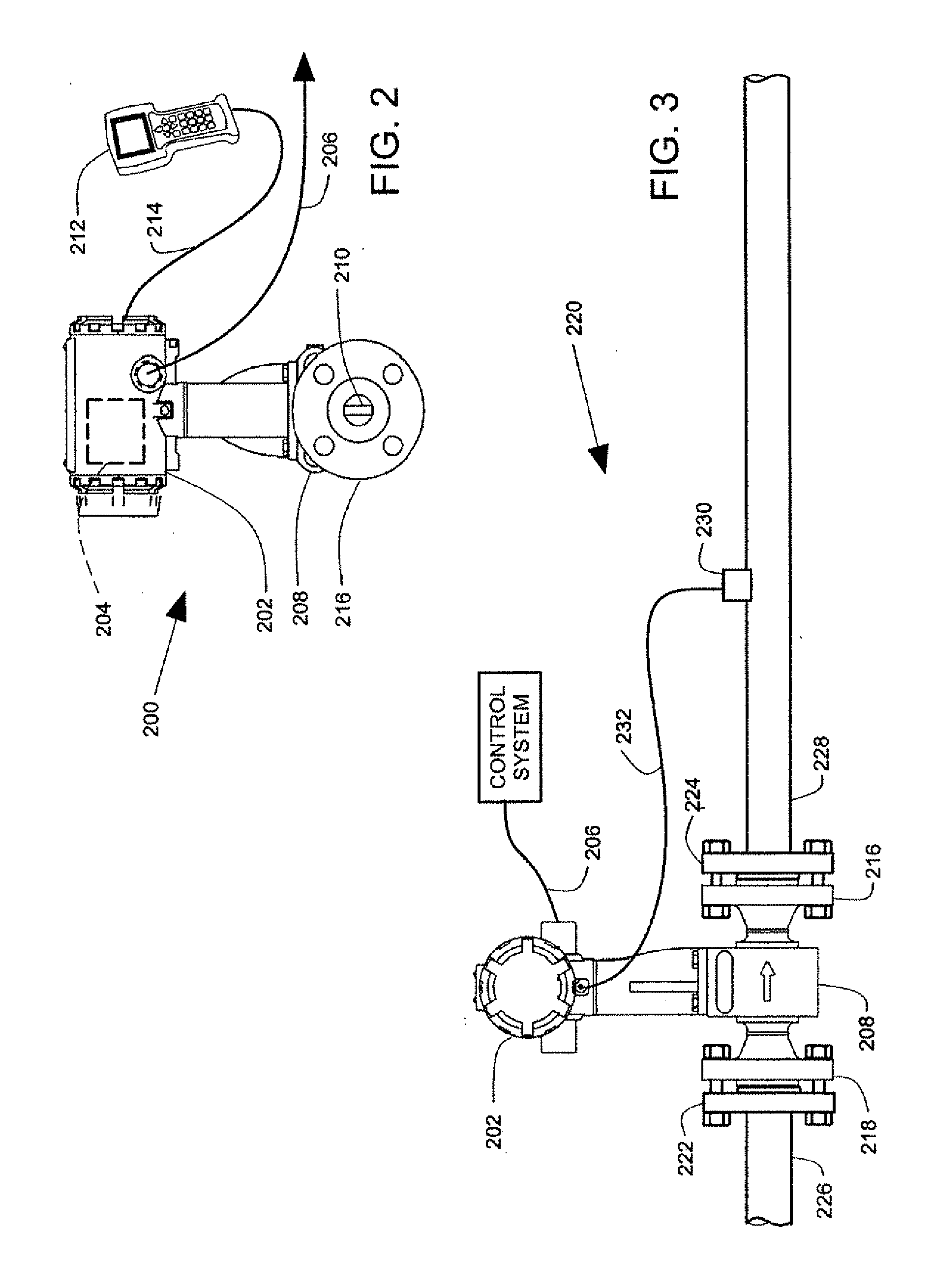
[0017]In the embodiments described below, a vortex flowmeter connects to a thermal junction in a thermowell assembly at a location that is remote from the vortex flowmeter. The vortex flowmeter receives data representing a thermal property of the thermowell assembly. A circuit in the vortex flowmeter receives an output of the thermal junction and a vortex sensor output. The circuit provides a flowmeter output that is compensated for temperature and that is compensated for the thermal property.

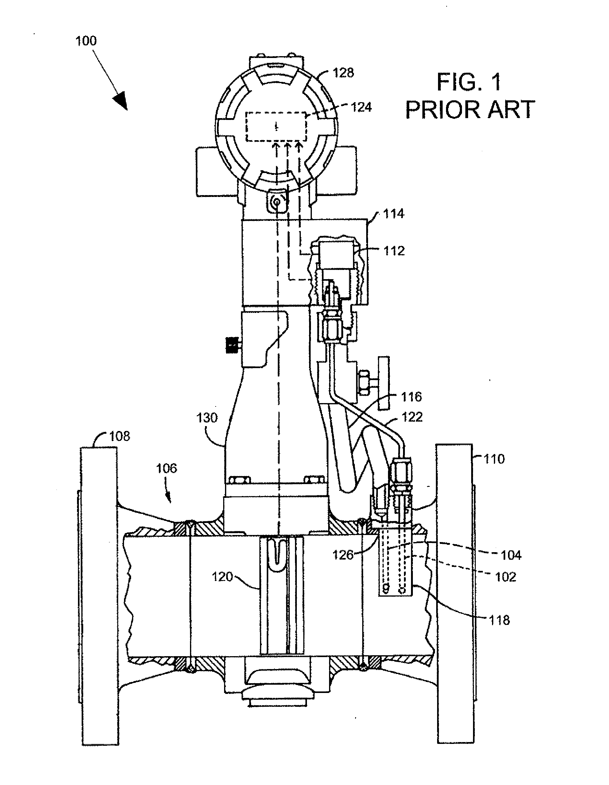
[0018]As illustrated in FIG. 1, a first type of vortex flowmeter includes a sensor for sensing fluid temperature, as disclosed for example in U.S. Pat. No. 6,658...


PUM


Abstract

A vortex flowmeter has a vortex sensor and terminals that receive a thermal junction output from a thermowell assembly that is remote from the vortex flowmeter. The vortex flowmeter has a data input that receives data representing a thermal property of the thermowell assembly. The vortex flowmeter has a circuit that receives the first thermal junction output and the vortex sensor output, and that provides a flowmeter output that is compensated for temperature and for the thermal property.

Description

CROSS-REFERENCE TO RELATED APPLICATION[0001]The present application is based on and claims the benefit of U.S. provisional patent application Ser. No. 60 / 875,498, filed Dec. 18, 2006, the content of which is hereby incorporated by reference in its entirety.BACKGROUND OF THE INVENTION[0002]In industrial process installations, vortex flowmeters are used to measure fluid flow rates through piping systems. The vortex flowmeter includes an electronic transmitter and a vortex meter housing. The vortex meter housing carries the fluid flow and supports a bluff body in the fluid flow. The vortex meter housing is generally cylindrical and fits between flanges in the piping system.[0003]Vortices are generated by fluid flow past the bluff. The occurrence of the vortices is generally proportional to fluid velocity. The vortex frequency is measured by the electronic transmitter and used to calculate a flowmeter output that indicates the flowrate.[0004]A first type of vortex flowmeter (described b...

Claims


Application Information

Patent Timeline
IPC IPC(8): G01F1/68
CPCG01F1/3209G01K17/12G01K1/14G01F1/86
Inventor SCHMIDT, ERIC C.FOSTER, JEFFRY D.
Owner MICRO MOTION INC
Why Eureka
Try Eureka