Non-destructive inspection instrument employing multiple sensor technologies in an integral enclosure

a sensor technology and non-destructive inspection technology, applied in the direction of instruments, transmission, using subsonic/sonic/ultrasonic vibration means, etc., can solve the problems of difficult access to inspection sites, travel to remote locations, and not often practical to have a sufficient inventory of ndi instrument types

Active Publication Date: 2012-10-18
OLYMPUS AMERICA
View PDF3 Cites 42 Cited by
  • Summary
  • Abstract
  • Description
  • Claims
  • Application Information

AI Technical Summary

Benefits of technology

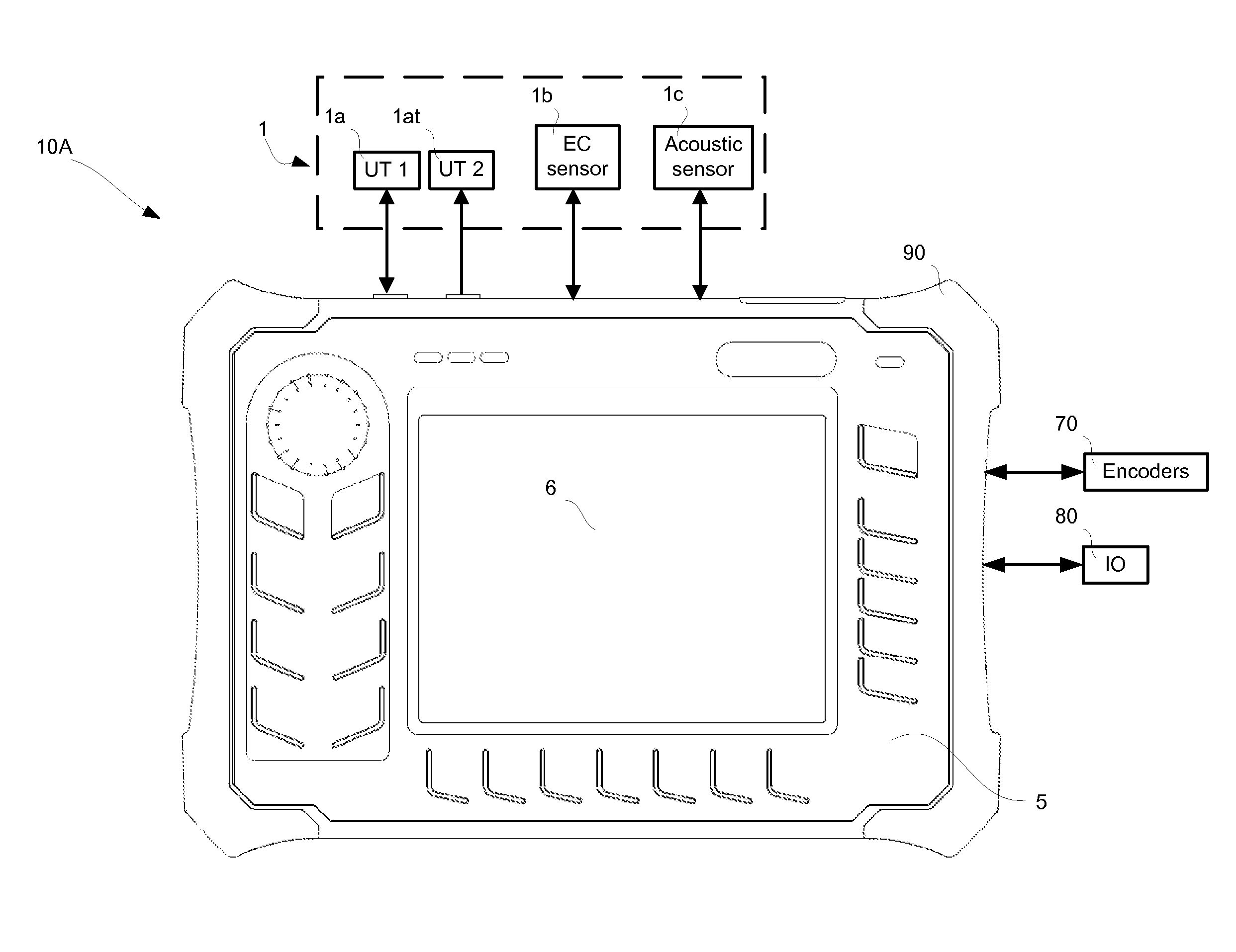
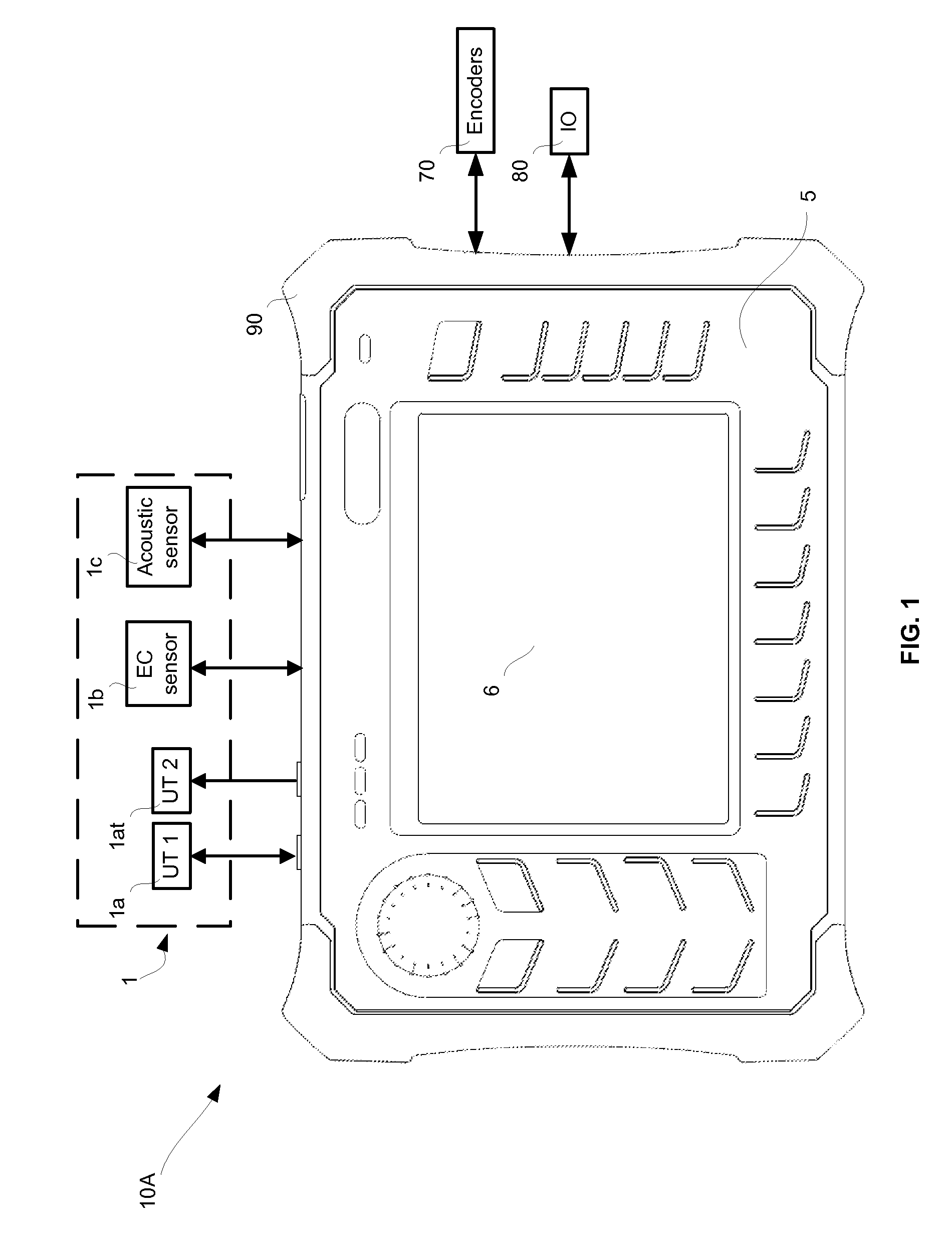
[0011]It is the general object of the present disclosure to overcome the problems associated with background art by introducing an economical, small, and compact inst

Problems solved by technology

Ready access to these instruments by inspection service providers is of paramount importance because inspection events are often time critical and the type of inspection technology required is not always known with much advance notice.
Due to economic constraints, it is not often practical to have a sufficient inventory of NDI instrument types to ensure that all inspection needs are met at any given time.
Another problem posed by the need for multiple NDI technologies concerns travel to remote and difficult to access inspections sites whether they are on land or at sea.
Boeing MAUS-V product provides the usage of multiple sensors; however it has the drawbacks of using a computer and different data processing tools for data acquired from different types of sensors.
The lack of using a common data acquisition and common data processing element in an integral and handheld enclosure presents an array of problems for field operation, including the weight and size of the product, the n

Method used


Image

  • Non-destructive inspection instrument employing multiple sensor technologies in an integral enclosure
  • Non-destructive inspection instrument employing multiple sensor technologies in an integral enclosure
  • Non-destructive inspection instrument employing multiple sensor technologies in an integral enclosure

Examples


embodiment 1

Alternate Embodiment 1

Parallel High Dynamic Range Receiver for UT Sensor Mode

[0079]Depicted in FIG. 4a, the subsequent description provides an embodiment with an alternative data acquisition circuitry 46, substituting data acquisition circuit 2 in FIG. 3. It should be noted that the entire description of the preferred embodiment shown in FIG. 3 applies to alternate embodiment 1 except for the description in the UT SENSOR OPERATING MODE section of the present disclosure that pertains to receiver sub-section 29.

[0080]Referring to FIG. 4a, receiver (Rx) circuitry 47 includes an alternate UT specific, parallel high dynamic range (PHDR) front-end circuit 800. Similar to the preferred embodiment, it also includes MUX 38 and ADC 36 that can be used by all three sensor types. Clock 28 in FPGA 19 may be adjusted to provide a range of clock signal frequencies to ADC 36, which for the UT sensor mode is preferably 100 MHz.

[0081]Detailed description of PHDR front-end circuit 800 is provided in U...

embodiment 2

Alternate Embodiment 2

Conventional Receiver for UT Sensor Mode

[0084]Alternate embodiment 2 of the present disclosure is now described in relation to FIG. 4b, in which another embodiment with an alternative data acquisition circuitry 39, substituting data acquisition circuit 2 in FIG. 3. More particularly, data acquisition circuitry 39 employs a front-end circuitry alternative to the sequential high-dynamic range circuit 104 in FIG. 3.

[0085]It should be noted that the entire description of the preferred embodiment shown in FIG. 3 applies to alternate embodiment 2 except for the description in the UT SENSOR OPERATING MODE section of the present disclosure that pertains to receiver circuitry 29 in FIG. 3.

[0086]Continuing with FIG. 4b, Receiver (Rx) circuit 40 includes UT specific circuit elements such as a calibration circuit (CAL) 41, a multi-pole switch 42, an attenuator 43, and VGA 44. MUX 38, filters 35, VGA 37 and ADC 36 are used by all three sensor types. Clock 28 in FPGA 19 may ...


PUM


Abstract

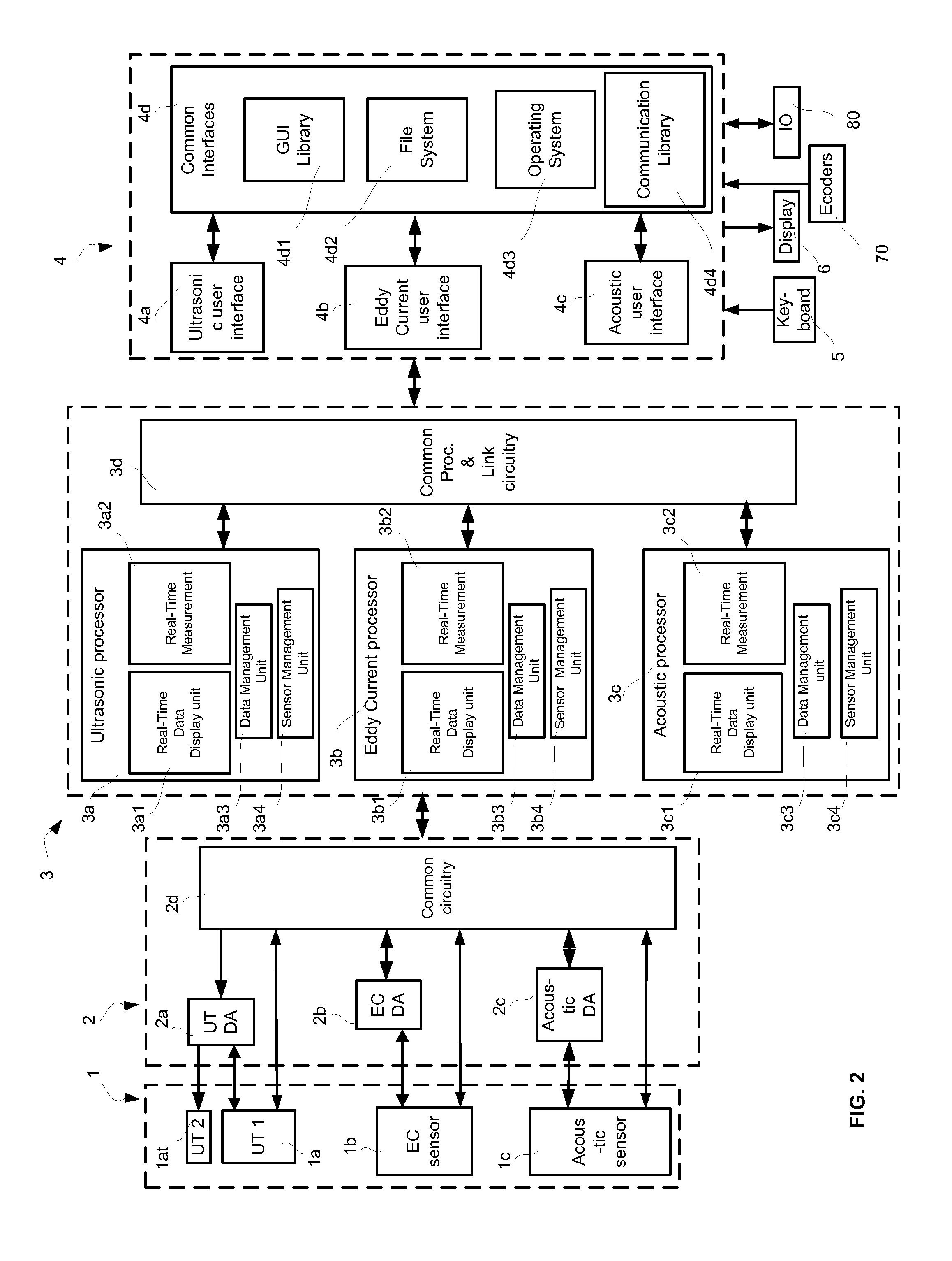
A non-destructive inspection (NDI) instrument includes a sensor connection system configured to receive test signals from at least two different types of NDI sensors which are configured to obtain test signals from an object being tested. The sensor connection system has sensor-specific connection circuits and at least one common sensor connection circuit. A data acquisition circuitry is coupled to the sensor connection and has sensor-specific data acquisition circuits and at least one common data acquisition circuit. It is further coupled to a common digital data processor which executes sensor-specific processing modules and at least one common processing module. A common display screen and user interface is coupled to the data processor and enables programs including sensor-specific user interface modules and at least one common user interface module. The sensor types preferably include all of or any combination of an ultrasound sensor, an eddy current sensor and acoustic sensor.

Description

BACKGROUND OF THE INVENTION[0001]The present disclosure relates to non-destructive inspection (NDI) instruments, and more particularly to an instrument that is operable with multiple NDI sensor technologies, any one of which may be selected by the user.[0002]Inspection service providers are among the largest users of NDI equipment. They have a broad customer base that requires many different inspection technologies to meet their inspection needs. For example, oil refineries require ultrasonic instruments to measure pipe and vessel wall conditions and detect flaws, aerospace companies require acoustic bond testing instruments to detect the composite material delamination, and eddy current instruments to detect cracks in metal surfaces of airplanes.[0003]Ready access to these instruments by inspection service providers is of paramount importance because inspection events are often time critical and the type of inspection technology required is not always known with much advance notice...

Claims


Application Information

Patent Timeline
IPC IPC(8): G06F15/00G01N27/9013
CPCG01B7/00G01B17/02G01N27/9046G01N2291/02854G01N29/043G01N2291/0258G01N27/9073
Inventor DRUMMY, MICHAEL
Owner OLYMPUS AMERICA
Why Eureka
Try Eureka