Direct current sensor

A DC current and sensor technology, applied in the direction of measuring current/voltage, instruments, measuring electrical variables, etc., can solve the problems of limiting the application and promotion of magnetic modulators, complex structure, low coercive force, etc., and improve the open-loop output characteristics , Good interchangeability, small size effect

Inactive Publication Date: 2005-02-16
HUAZHONG UNIV OF SCI & TECH
View PDF0 Cites 39 Cited by
  • Summary
  • Abstract
  • Description
  • Claims
  • Application Information

AI Technical Summary

Problems solved by technology

This amplifier has serious disadvantages: when the number of turns of the DC winding is large, according to the principle of transformer effect, the AC voltage in the excitation winding will induce an alternating voltage in the DC winding. In order to effectively suppress the induced voltage in the DC control loop, it is necessary to Putting an inductor in series in the circuit or having to use a double core structure will make its structure complex, bulky and heavy
In order to obtain the excellent performance of the magnetic modulator, the performance of the ferromagnetic mate

Method used


Image

  • Direct current sensor
  • Direct current sensor
  • Direct current sensor

Examples


Embodiment Construction

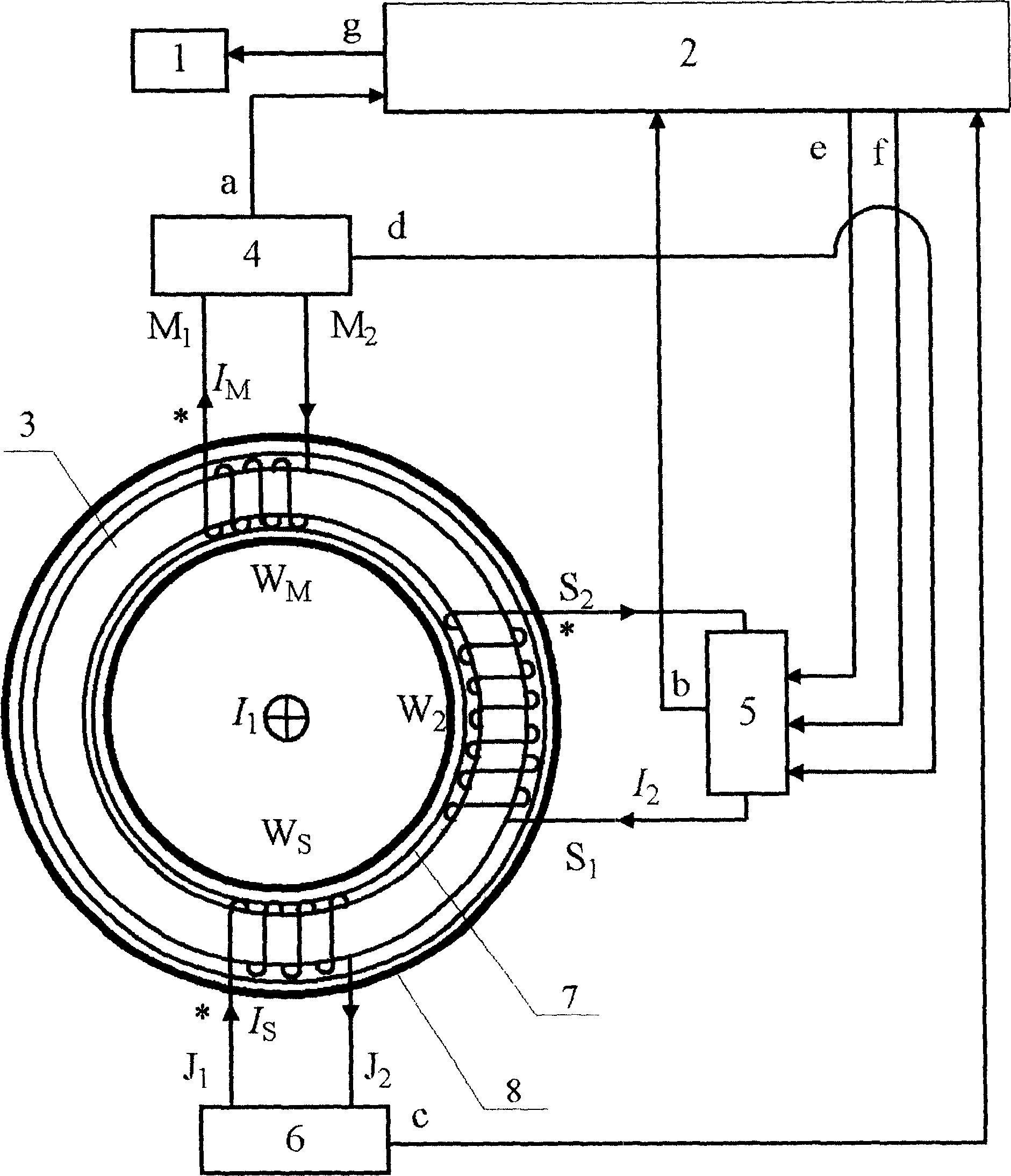
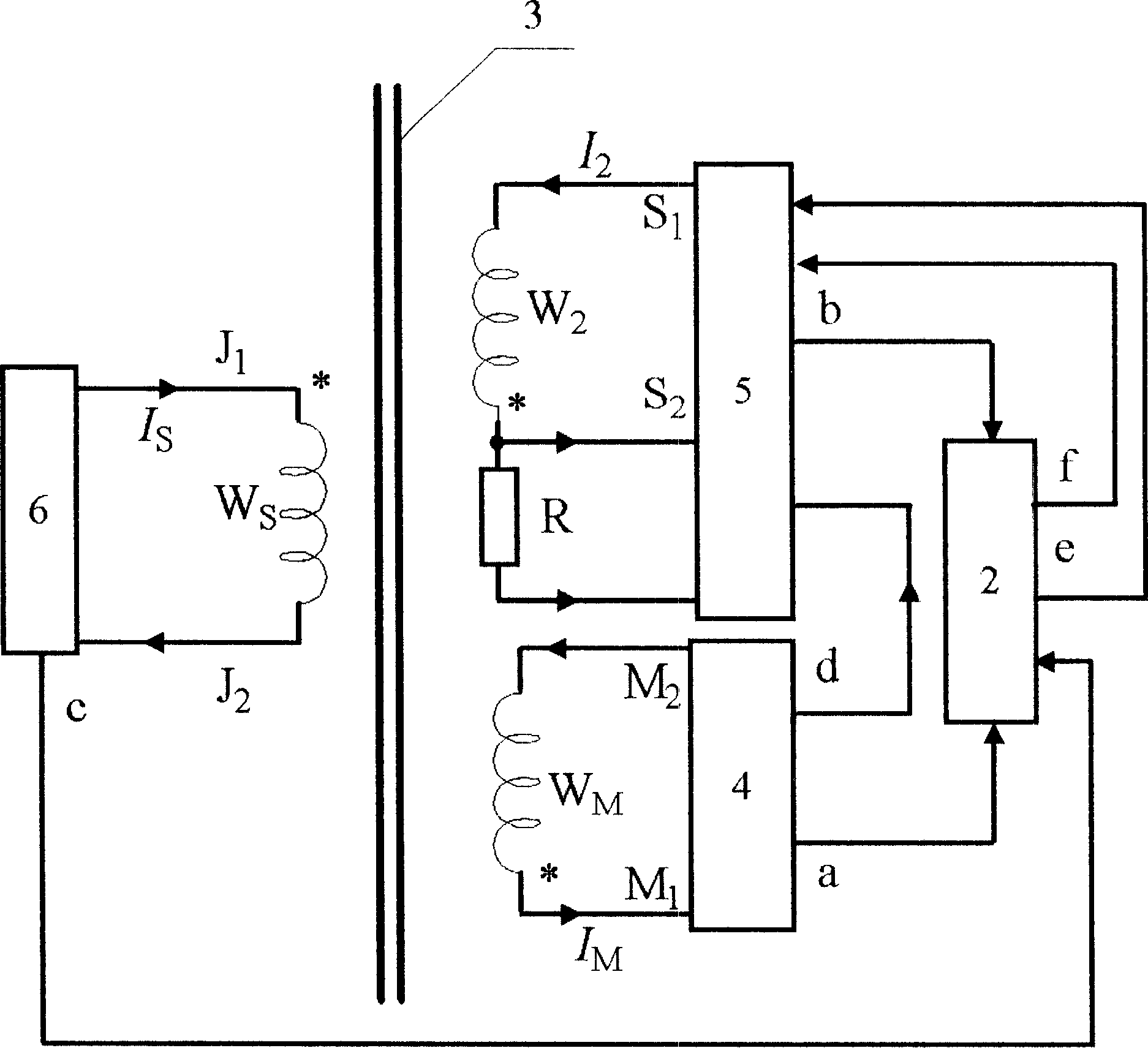
[0027] Depend on figure 1 , figure 2 Shown, W M To detect the coil, the current flowing through the coil is I M , W 2 is the feedback winding, the current flowing in this winding is I 2 , W S To excite the winding, the current flowing in this winding is I S , 1 is the monitor, 2 is the computer, 3 is the ring core, 4 is the detection coil W M processing circuit, 5 is the feedback winding W 2 processing circuit, 6 is the excitation winding W S Processing circuit, 7 is the shielding layer of the sensor, 8 is the outer protective ring of the sensor, I 1 is the measured DC, * indicates the detection coil W M , excitation winding W S and the feedback winding W 2 end of the same name.

[0028] Wind the excitation winding W on the ring core 3 S , Feedback winding W 2 and detection coil W M , at the detection coil W M The two ends of the processing circuit 4, in the feedback winding W 2 The two ends of the processing circuit 5, in the excitation winding W SThe two-e...


PUM


Abstract

The present invention discloses a DC curren sensor. In said sensor a detection coil is added, said sensor adopts single-core three-winding structure, when a DC bias magnet is existed in the magnetic core, the induced potential obtained by detection coil can produce positive-negative half-wave unsmmetrical waveforms, said waveforms can be converted into the voltage signal of difference of positive-negative half-wave effective values, after voltage/current conversio, said signal can be fed into feedback winding, said feedback winding cap produce the DC magnetic potential whose direction is opposite to that of magnetic patential produced by detected direct current to balance the bias magnetic potential produced by detected direct current to form 'null-flux' state, so that it can obtain the detected direct current intensity so as to implement the detection of direct current.

Description

technical field [0001] The invention relates to a direct current sensor, which is suitable for detecting direct current including the following aspects: such as used in power electronic equipment for current feedback, cut-off control, steady current regulation, direct current side overcurrent, power system and electrolysis industry, etc. DC current signal detection. Background technique [0002] In DC transmission system, frequency conversion speed control device, UPS power supply, inverter welding machine, electrolytic plating, CNC machine tool, microcomputer monitoring system, power grid monitoring system and various fields that need to isolate and detect DC current, it is necessary to accurately detect and control DC current. The fundamental guarantee for the safe and reliable operation of the equipment and the first problem to be solved. [0003] Current measurement equipment such as DC current comparators, DC transformers, and shunts have been developed; some measureme...

Claims


Application Information

Patent Timeline
IPC IPC(8): G01R19/00
Inventor 李维波毛承雄陆继明
Owner HUAZHONG UNIV OF SCI & TECH
Why Eureka
Try Eureka