Micro-Impact Testing Apparatus

a micro-impact and testing apparatus technology, applied in the direction of measuring devices, material strength using single impulsive force, instruments, etc., can solve the problems of varying thermal operating conditions, process that is not cost effective when done solely for testing purposes, and the present industry practice of solder ball shearing using a standard ball shearing tester is not desirabl

Inactive Publication Date: 2008-06-19
AGENCY FOR SCI TECH & RES +1
View PDF5 Cites 19 Cited by
  • Summary
  • Abstract
  • Description
  • Claims
  • Application Information

AI Technical Summary

Problems solved by technology

Portable devices are more likely to experience shocks from impacts and varying thermal operating conditions arising from the different environments in which they may be used.
However, the JEDEC test requires the assembling of the component onto a PCB, a process that is not cost effective when done solely for testing purposes.
With respect to testing, the present industry practice of solder ball shearing using a standard ball shear tester is not desirable for at least two reasons.
Firstly, the ball shear tester is unable to effectively induce the desired mode of failure testing due to its low shear speed.
Secondly, the minute specimen of the solder ball represents a challenge, as its size and geometry prevent accurate characterization of the failure when using stan

Method used


Image

  • Micro-Impact Testing Apparatus
  • Micro-Impact Testing Apparatus
  • Micro-Impact Testing Apparatus

Examples


Embodiment Construction

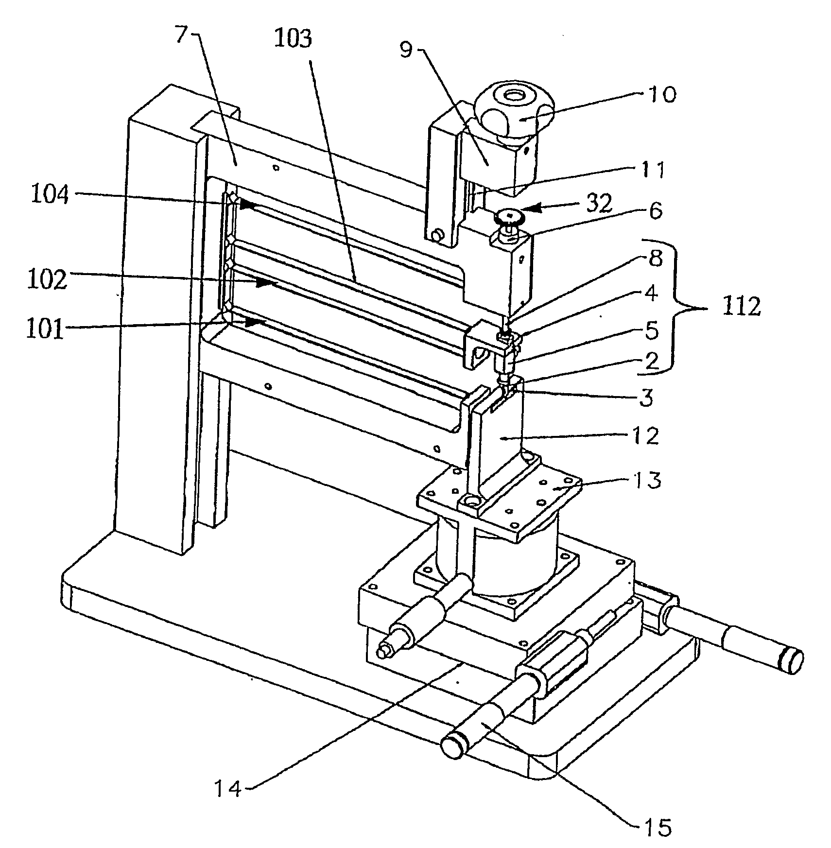
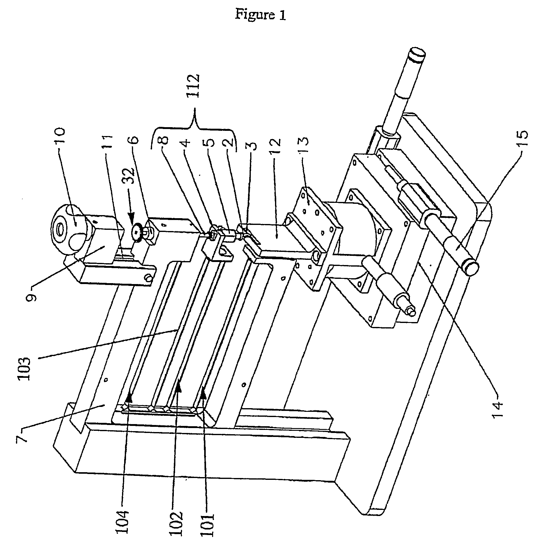
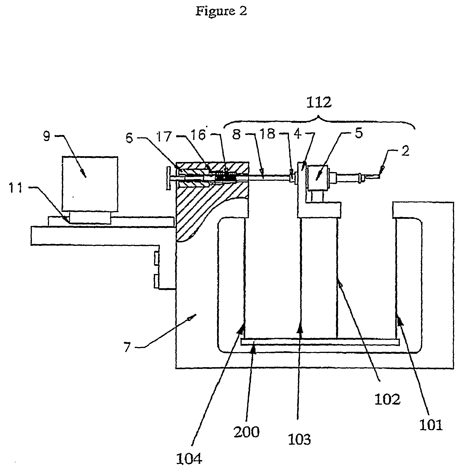
[0010]The impact head, according to the above embodiment of the impact testing apparatus, is moveable transversally with respect to the first and second flexural springs along a linear line between a spring-loaded position (loaded position) and an impact position thereof. Further, the specimen holder is aligned with the impact device such that the test specimen received in said test specimen holder is arranged in said impact position of the impact head. This enables the impact head to precisely impact the specimen after traveling from its loaded position towards its impact position along said linear line. The linear motion is important in order for the impact head to provide for the required precise shear force to the test specimen upon release. The linear motion of the impact head is also necessary to enable the testing apparatus to carry out tests on test specimens of minute size and geometry.

[0011]In addition, further advantages of using the above-mentioned arrangement, including...


PUM


Abstract

A micro-impact testing apparatus for measuring the impact characteristics of a microelectronics specimen exposed to an impact thereon. The apparatus comprises of a specimen holder for receiving a specimen to be tested, and an impact device. The impact device comprises of an impact head, a support member, at least one connecting element and a first flexural spring. The support member is connected to the connecting element in that the first flexural spring is firmly attached with its one end to the support member and with its other end to the connecting element. A second flexural spring, being at least substantially identical to said first flexural spring, is firmly attached with its one end to the connecting element and with its other end to the impact head so that the ends of the first and second flexural springs define, in an unloaded state of the flexural springs, a rectangle. The impact head is moveable transversally with respect to the first and second flexural springs along a linear line between a spring-loaded position and an impact position thereof. The specimen holder is aligned with the impact device such that the specimen is arranged in said impact position of the impact head so that the impact head is capable of impacting on the specimen after traveling from its loaded position towards its impact position along said linear line upon release thereof from said loaded position.

Description

FIELD OF INVENTION[0001]The present invention relates to the field of impact testing microelectronic interconnections, more specifically, to an apparatus for testing the impact properties of said microelectronic interconnections.BACKGROUND OF THE INVENTION[0002]An ever-increasing number of portable devices, such as mobile telephones, portable media players and portable computers, for example, are now available to consumers. Accordingly, as a device becomes portable, the usage conditions that it is subjected to will vary greatly, such as from a device under static use such as a desktop computer, for example. Portable devices are more likely to experience shocks from impacts and varying thermal operating conditions arising from the different environments in which they may be used. In realization of this, the microelectronics industry has adopted standards to gauge how well the various microelectronic components, such as printed circuit boards (PCB) and their mounted components, fair u...

Claims


Application Information

Patent Timeline
IPC IPC(8): G01N3/30
CPCG01N2203/0286G01N3/307G01N3/30
Inventor WONG, EE HUARAJOO, RANJAN S/OTSAI, KUO TSING
Owner AGENCY FOR SCI TECH & RES
Why Eureka
Try Eureka