Method and system for limiting torque load associated with an implement

a technology of torque load and implement, which is applied in the direction of fluid couplings, thinning machines, instruments, etc., can solve the problems of undesirable noise, damage to the cylinder or other components of the linkage system, and the operation of the hydraulic cylinder can be difficult to achieve the effect of reducing the speed of the implement system

Active Publication Date: 2008-06-19
CATERPILLAR INC
View PDF9 Cites 18 Cited by
  • Summary
  • Abstract
  • Description
  • Claims
  • Application Information

AI Technical Summary

Benefits of technology

[0009]In yet another aspect, the present disclosure is directed to a method of limiting the motion of a hydraulic cylinder on a machine. The method may include sensing a speed associated with a power source, wherein the power source is related to a machine and configured to drive a hydraulic pump associated with the machine and sensing a position associated with an implement system, wherein the implement system is associated with the machine, a hydraulic cylinder, and the hydraulic pump. The method may further include receiving a command to provide a flow of fluid from the hydraulic pump to the implement system to impart motion to the implement system and reducing the flow of fluid from the hydraulic pump, resulting in a reduced velocity of the implement system, when the speed associated with the power source falls below a power source speed threshold and the position associated with the linkage falls within a predetermined positional proximity of a stop point associated with the implement system.

Problems solved by technology

Problems can be encountered in the operation of a hydraulic cylinder if a piston within the hydraulic cylinder impacts against an end structure of the hydraulic cylinder.
Such impacts can cause undesirable noise, and damage to the cylinder or other components of the linkage system.
Although the fluid cylinder system of the '793 patent may provide position and velocity information for controlling electronically actuated hydraulic valves to mitigate impacts (e.g., noise and damage to cylinders), the fluid cylinder system operates at all times (i.e., no determination of when limiting should be turned off), which may cause operator frustration and a loss of productivity because of a slowing implement as the implement nears a stop point.

Method used


Image

  • Method and system for limiting torque load associated with an implement
  • Method and system for limiting torque load associated with an implement
  • Method and system for limiting torque load associated with an implement

Examples


Embodiment Construction

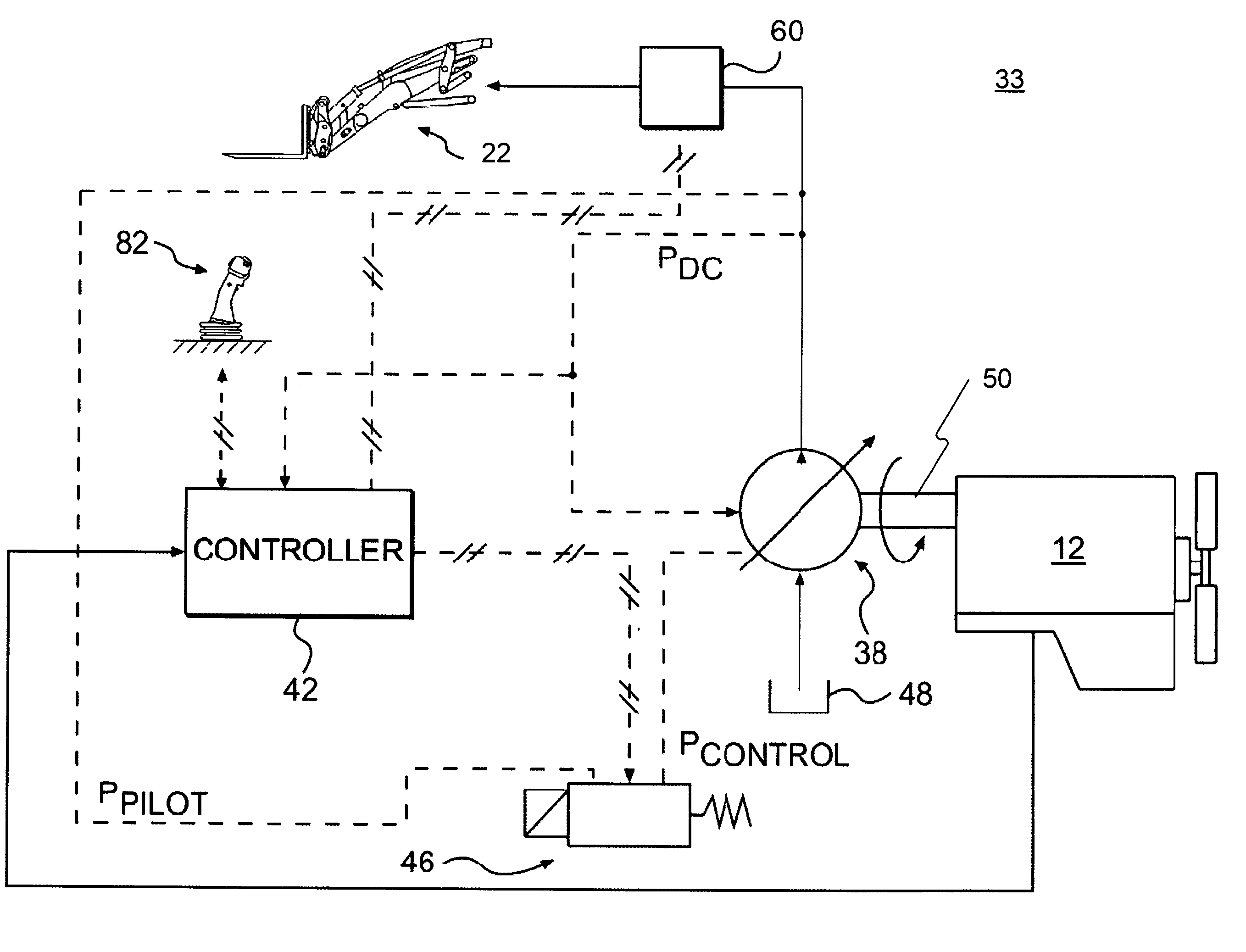
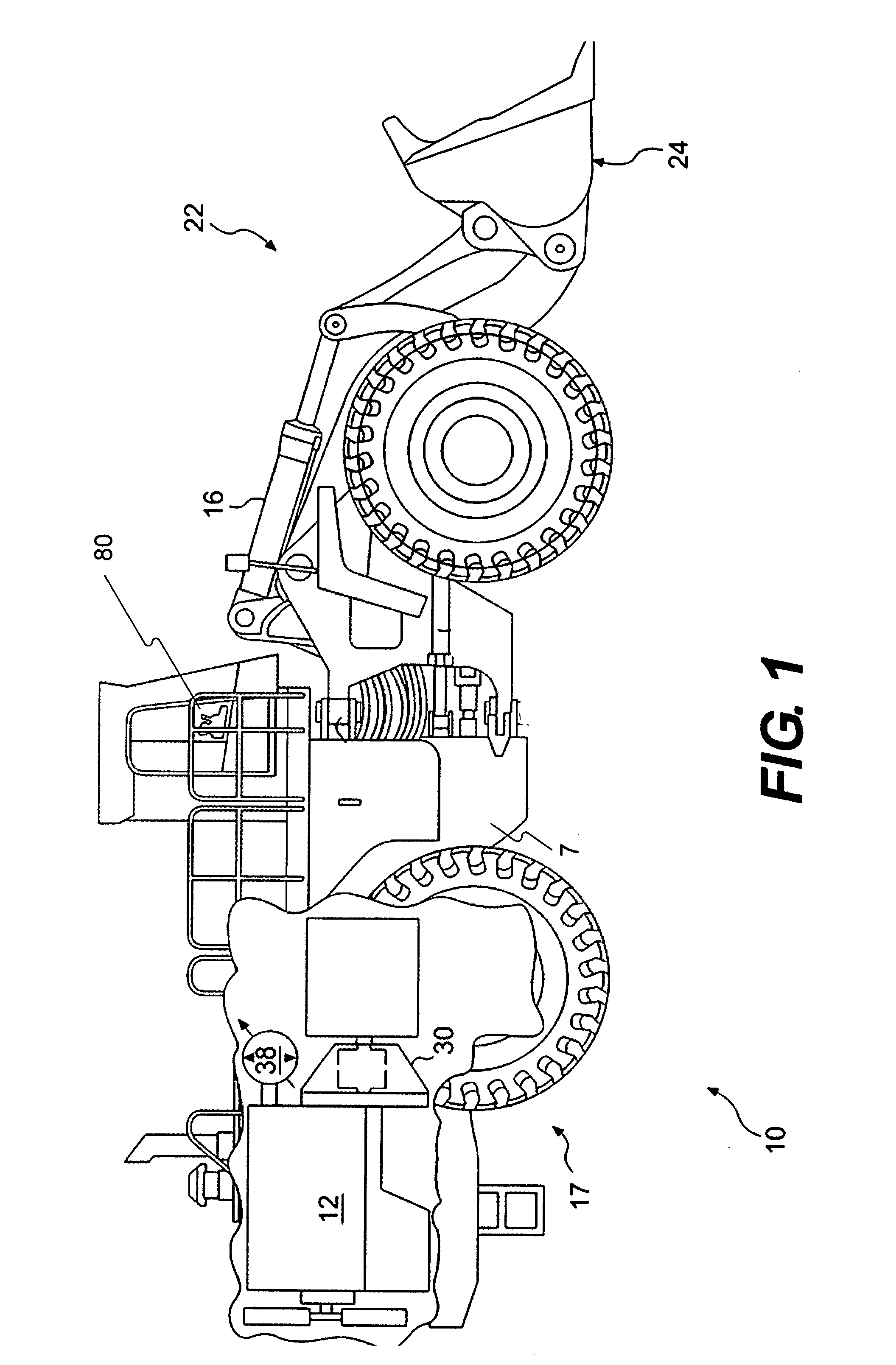
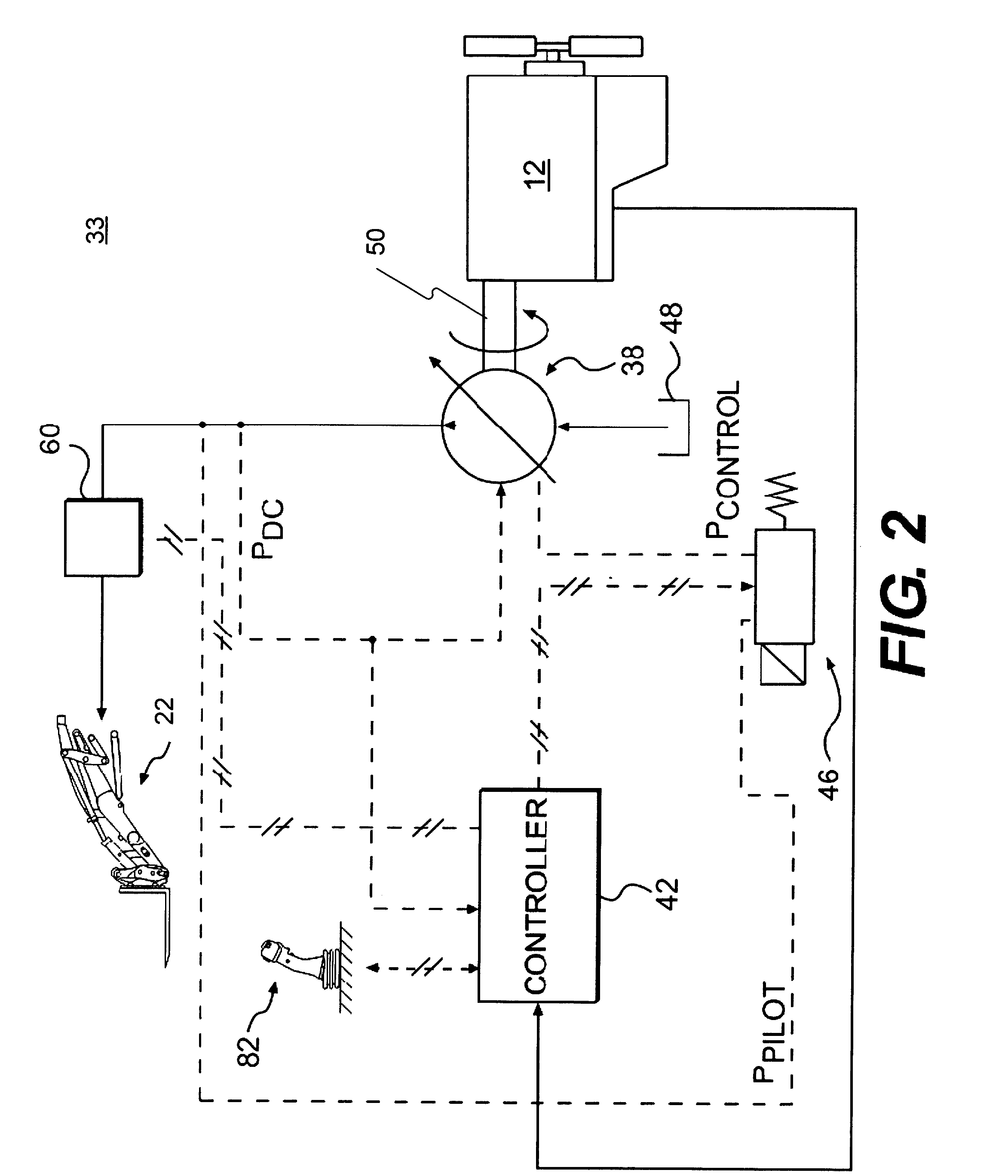
[0013]FIG. 1 illustrates an exemplary embodiment of a machine 10. Machine 10 may be a mobile machine that performs some type of operation associated with an industry such as mining, construction, farming, or any other industry known in the art. For example, machine 10 may be an earth moving machine such as a wheel loader, a dump truck, a backhoe, a motor grader, or any other suitable machine. Machine 10 may include a power source 12, a frame 7, an operator interface 80, a hydraulic pump 38, and a transmission 30 connected to at least one driven traction device 17. Machine 10 may further include one or more implement systems 22.

[0014]Power source 12 may be an engine such as, for example, a diesel engine, a gasoline engine, a gaseous fuel powered engine such as a natural gas engine, or any other engine apparent to one skilled in the art. Power source 12 may also embody another source of power such as a fuel cell, a power storage device, or any other source of power known in the art.

[0...


PUM


Abstract

A method for reducing a torque load associated with an implement includes determining a speed associated with a power source, wherein the power source is configured to provide power to a hydraulic pump, determining a position associated with an implement system, and limiting a flow associated with the hydraulic pump based on the speed associated with the power source and the position associated with the implement system.

Description

TECHNICAL FIELD[0001]This disclosure relates generally to limiting torque load associated with an implement and, more particularly, to a system and method for limiting torque load associated with an implement based on power source speed and implement position.BACKGROUND[0002]Machines such as, for example, dozers, loaders, excavators, motor graders, and other types of heavy machinery use linkage systems to accomplish a variety of tasks. These linkage systems often include hydraulic cylinders. Problems can be encountered in the operation of a hydraulic cylinder if a piston within the hydraulic cylinder impacts against an end structure of the hydraulic cylinder. Such impacts can cause undesirable noise, and damage to the cylinder or other components of the linkage system.[0003]Limiting the motion of an implement (i.e., snubbing) has been utilized to limit damage and noise associated with such implement operation. Limiting may have two steps: (1) determining when to limit motion and (2)...

Claims


Application Information

Patent Timeline
Patent Type & Authority Applications(United States)
IPC IPC(8): E02F9/20G06F19/00
CPCE02F9/2296E02F9/2214
Inventor PALMER, MARVIN KENTBUDDE, STEVEN CONRADKAMISETTY, SRIVIDYA LAVANYA
Owner CATERPILLAR INC
Why Eureka
Try Eureka