Beater for a rotary shredder

a technology of rotary shredder and beater, which is applied in the field of shredding technology, can solve the problems of heavy wear on the cutting edge of the cutting head, and achieve the effects of reducing wear, avoiding weakening of the relative thin cutting head, and increasing the beating

Inactive Publication Date: 2008-06-19
DOPPSTADT FAMILIENHOLDING GMBH
View PDF2 Cites 5 Cited by
  • Summary
  • Abstract
  • Description
  • Claims
  • Application Information

AI Technical Summary

Benefits of technology

[0014]Thus, instead of providing a recess, the cutting head contains a projection. With this a weakening of the relative thin cutting head is avoided. On the contrary the cutting head is strengthened by the projection and its additional material. The recess complementary to the projection is provided by the more massive base body. The base body is formed having mass substantially greater than the cutting head. The base body is subject to reduced wear and therefore only has to be changed sparingly, if at all. The base body should have a significant mass for increasing the effect of beating. Normally the cutting head is made of harder material. Aside from the risk of breakage the cutting head is subject to heavy wear upon the cutting edge and has to be exchanged often. Thus the cutting head should not contain an unnecessary amount of material and just ensure a proper transfer of forces to the base body.

Problems solved by technology

Aside from the risk of breakage the cutting head is subject to heavy wear upon the cutting edge and has to be exchanged often.

Method used


Image

  • Beater for a rotary shredder
  • Beater for a rotary shredder
  • Beater for a rotary shredder

Examples


Embodiment Construction

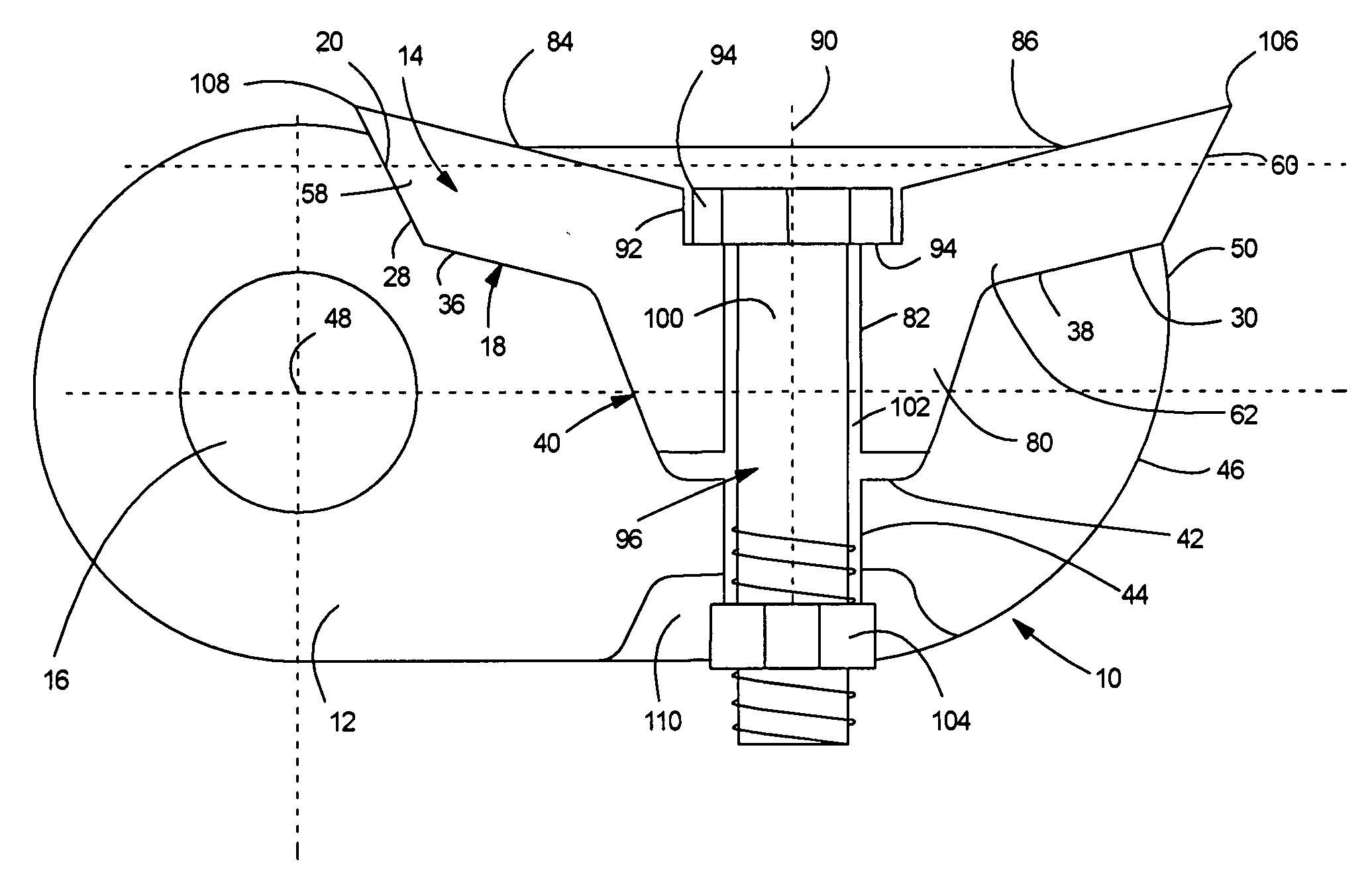
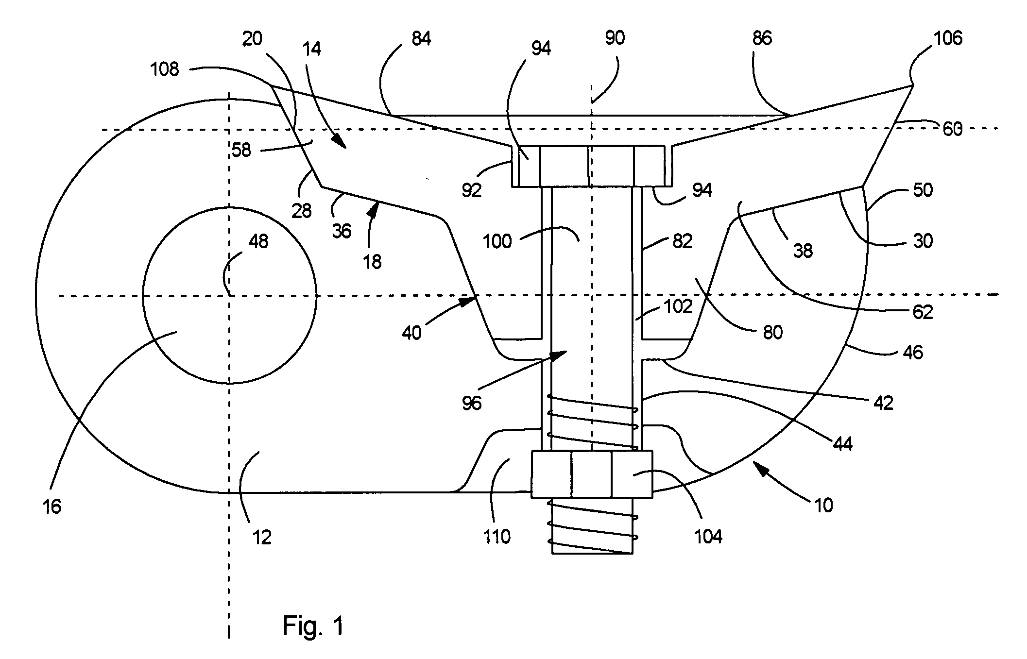
[0021]The beater or flail mallet 10 comprises a base body 12 and a cutting head 14 connected to each other. The base body 12 has an elongated configuration. At one end the base body a bore 16 is provided for a pivot bearing. The beater or flail mallet is pivoted by means of a pivotal bearing to a rotor together with other similar beaters.

[0022]The base body 12 provides a support surface for the cutting head 14. Generally the support surface is referred to with the reference number 18. As shown in FIG. 1, adjacent to the thickened end part of the base body 12 containing the bore 16, the support surface 18 provides a step with an inclined area 20. Adjacent to that, the support surface 18 forms a shallow four-sided truncated pyramidal recess 22. The base face of the truncated pyramid is rectangular having two longitudinal sides 24, 26 extending in longitudinal direction of the beater or flail mallet 10 along the side surfaces of the base body 12 and two lateral sides 28 and 30 extendin...


PUM


Abstract

A beater for a rotary shredder comprises an oblong base body with a pivot bearing adapted for pivotal connection of the beater to a rotor. A cutting head is formed with protruding cutting edges on opposite ends supported by the base body via the support surface. Complementary interlocking structures are provided by the support surface on the support surface and the cutting head. A releasable connection passes through the complementary structures connecting the base body with the cutting head. The complementary structures are provided by a recess formed in the support surface of the base body and a thereto complementary projection of the cutting head.

Description

[0001]This is a continuing application of pct application PCT / EP2006 / 061966 filed MAY 2,2006 which claims priority of GERMAN PATENT application DE 10 2005 023 339.2 filed MAY 17,2005.FIELD OF THE INVENTION[0002]The invention relates in general to shredding technology, and more specifically it relates to a novel design of a beater or a flail mallet adopted for use with a rotary shredder.BACKGROUND OF THE INVENTION[0003]Rotary shredders contain a rotating rotor. Beater or flail mallets are pivoted to this rotating rotor. The beater or flail mallets are pivotable around axes which are in parallel with the axis of rotation of the rotor. During a rotation of the rotor the beater or flail mallets are pulled outward by the centrifugal force. Then they hit material to be comminuted or shredded like a hammer while rotating. For example, such rotary shredders are used for comminuting waste wood. If a piece of material is not comminuted by a beater or flail mallet immediately, the beater or fl...

Claims


Application Information

Patent Timeline
Patent Type & Authority Applications(United States)
IPC IPC(8): B02C13/28
CPCB02C13/28
Inventor DOPPSTADT, FERDINAND
Owner DOPPSTADT FAMILIENHOLDING GMBH
Why Eureka
Try Eureka