

Shock absorbing connector
a technology of shock absorption and connector, which is applied in the direction of dynamo-electric machines, magnetic circuit rotating parts, magnetic circuit shapes/forms/construction, etc., can solve the problems of shaft vibration and unwanted noise, and achieve the effect of reducing shaft vibration and motor nois
- Summary
- Abstract
- Description
- Claims
- Application Information
AI Technical Summary
Benefits of technology
Problems solved by technology
Method used
Image

Examples
first embodiment
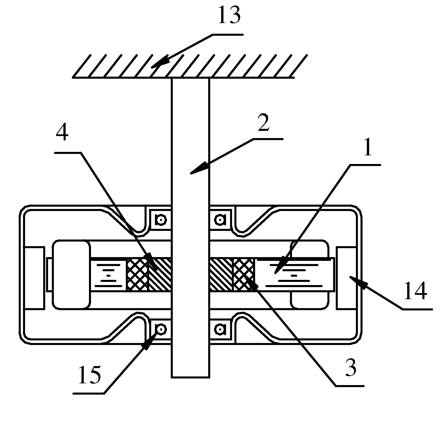
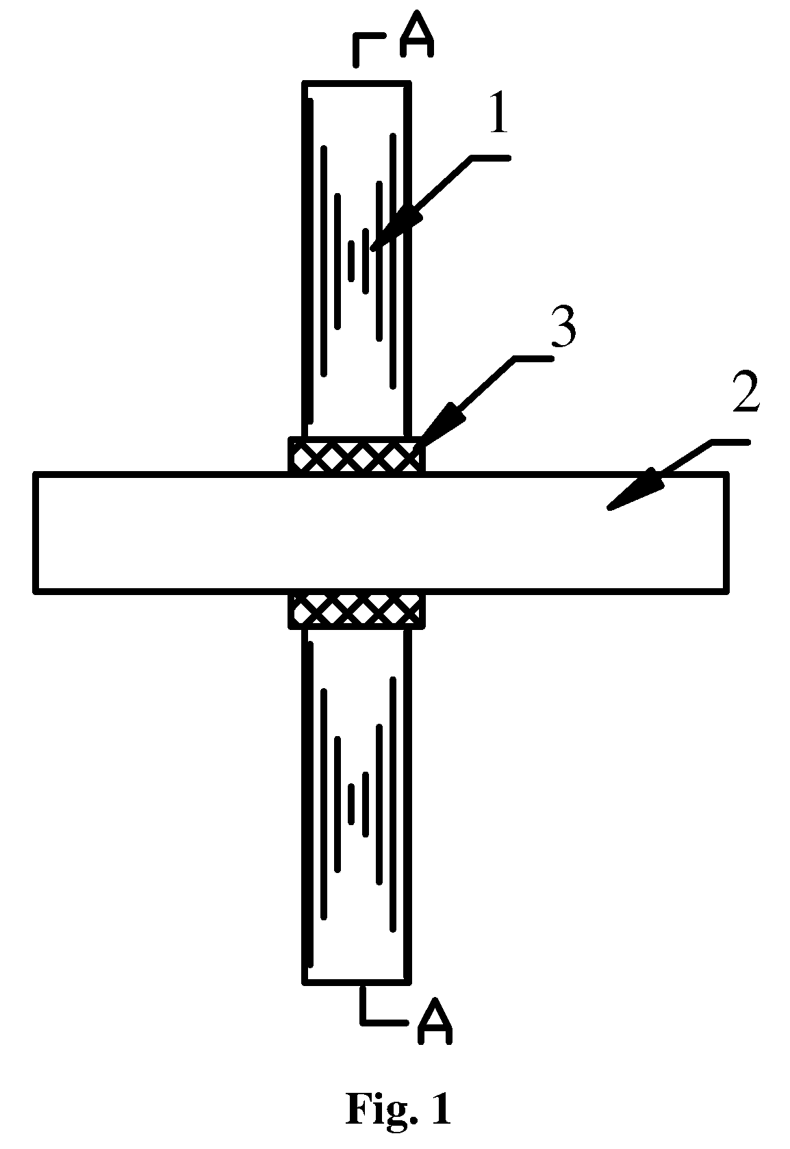
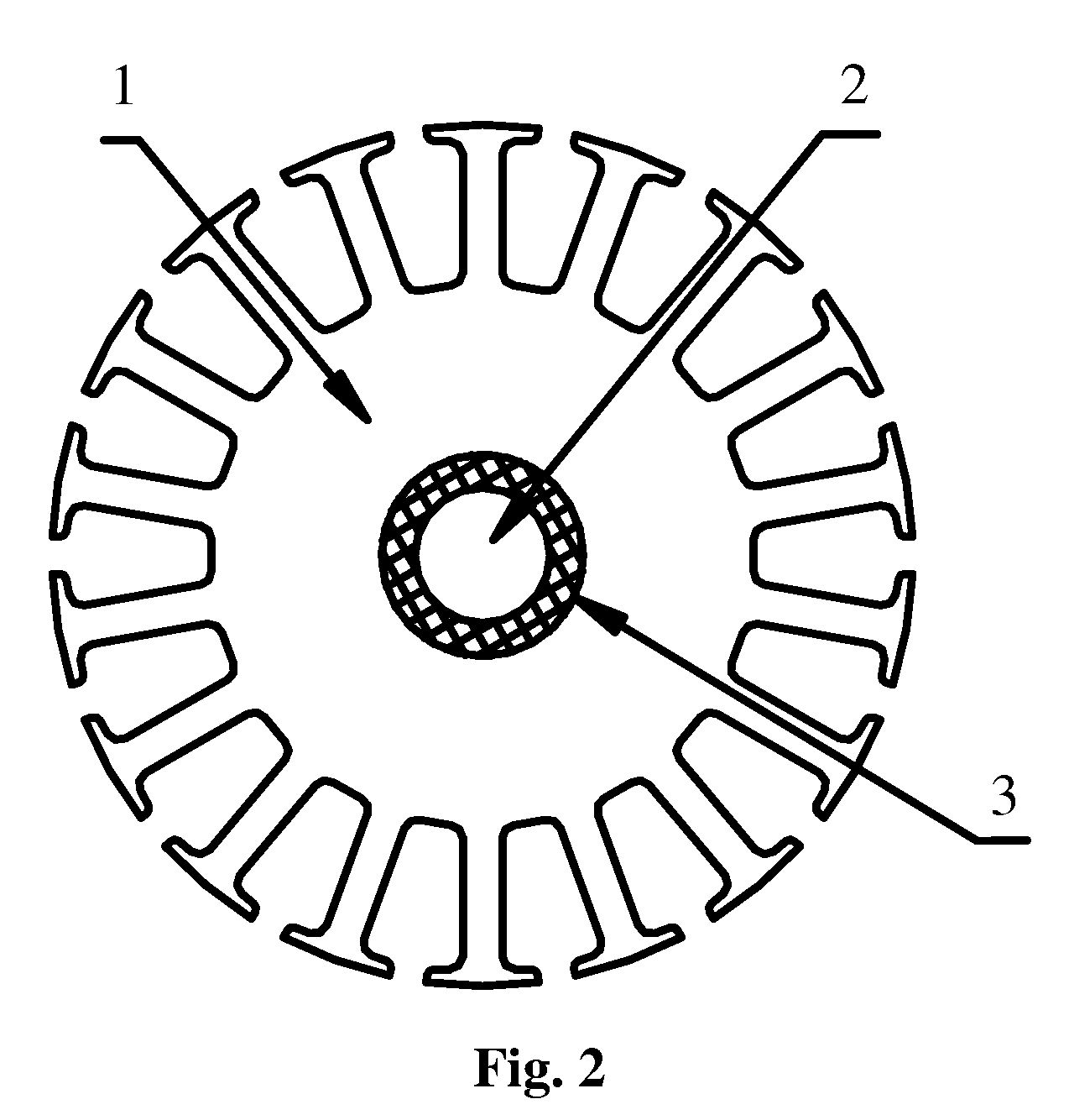
[0042]As shown in FIGS. 1 and 2, in the invention, the shock-absorbing connector is an injected rubber block 3 disposed between the stator core 1 and the shaft 2. Mechanical forces exerted on the stator core 1 by the rotor are transferred onto the shaft 2 via the injected rubber block 3. During this process, the injected rubber block 3 absorbs most of the unbalanced forces and in doing so it reduces vibration of the stator core 1 and the shaft 2.
second embodiment
[0043]As shown in FIGS. 3 and 4, in the invention, the shock-absorbing connector comprises a shaft sleeve 4 and an injected rubber block 3. The shaft 2 is tightly fixed inside the shaft sleeve 4 and the injected rubber block 3 is disposed between the shaft sleeve 4 and the stator core 1.
[0044]As shown in FIG. 10, a plurality of grooves 12 for receiving the injected rubber block 3 are disposed on an outer surface of the shaft sleeve 4 and an inner surface of the stator core 1. This prevents the injected rubber block 3 from sliding and reduces shock.
[0045]As shown in FIG. 5, a pair of retainers 8 is disposed at both sides of the injected rubber block 3, and press against the stator core 1 and the shaft sleeve 4 so as to immobilize the stator core 1 and the shaft sleeve 4 in an axial direction with respect to each other. In this way, as the stator core 1 is imposed with unbalanced counterforces, the counterforces will be transferred to the shaft sleeve 4 and the shaft 2 via the injecte...
fourth embodiment
[0047]As shown in FIGS. 8 and 9, in the invention, the shock-absorbing connector comprises a shaft sleeve 4, a plurality of rubber rods 5 and rivets 6. The shaft 2 is tightly fixed in the shaft sleeve 4. A plurality of grooves 12 for receiving the rubber rods 5 are disposed on an outer surface of the shaft sleeve 4 and an inner surface of the stator core 1, and the rivet 6 passes through the rubber rod 5. A pair of clamping plates 9 is disposed on an outer surface of the rubber rod 5, and the rivet 6 is rivet-connected to the clamping plates 9, so as to fix the stator core 1 and the shaft sleeve 4 together. Alternatively, in the absence of a clamping plate, a part of the rivet 6 protruding out of the stator core 1 may be bent to fix the stator core 1 and the shaft sleeve 4. During this process, the rubber rod 5 absorbs most of the unbalanced counterforces and in doing so it reduces vibration of the stator core 1 and the shaft 2.
[0048]As shown in FIG. 11, the shaft 2 is usually affix...
PUM
 Abstract
Description
Claims
Application Information