Method of sensing high surface temperatures in an aircraft

a technology of high surface temperature and aircraft, applied in the field of temperature sensing, can solve the problems of limited types of commercial temperature sensing labels that are surface mounted to an object, current temperature limitation of these types of temperature indicating paint, and inability to accurately detect the type of temperature indicators

Inactive Publication Date: 2008-06-19
HONEYWELL INT INC
View PDF11 Cites 18 Cited by
  • Summary
  • Abstract
  • Description
  • Claims
  • Application Information

AI Technical Summary

Benefits of technology

[0008]Other independent features and advantages of the improved method of sensing high surface temperatures will become apparent from the following detailed description, taken in conjunction with the accompanying drawings which illustrate, by way of example, the principles of the invention.

Problems solved by technology

Currently, these types of commercial temperature sensing labels that are surface mounted to an object are limited to sensing temperatures only up to approximately 300° C.
Due to the chemical composition of the temperature indicating paint, the current temperature limitation of these types of temperature indicating paints is at extremely high temperatures, typically between 1050° C. to 1350° C. During use, the temperature indicating paint is applied directly to the surface of the object in which it is desired to monitor the surface temperature.
Although these types of temperature sensors are capable of indicating elevated surface temperatures of an object or objects, they are not able to indicate elevated surface temperatures that fall in the range of approximately 300° C. to 400° C. In addition, many of these types of temperature indicators are not accurate in that they may be exposed to harmful external conditions, such as fluid, humidity, sand, or the like that surround the object or objects being monitored.

Method used


Image

  • Method of sensing high surface temperatures in an aircraft
  • Method of sensing high surface temperatures in an aircraft
  • Method of sensing high surface temperatures in an aircraft

Examples


Embodiment Construction

[0014]The following detailed description of the invention is merely exemplary in nature and is not intended to limit the invention or the application and uses of the invention. Furthermore, there is no intention to be bound by any theory presented in the preceding background of the invention or the following detailed description of the invention.

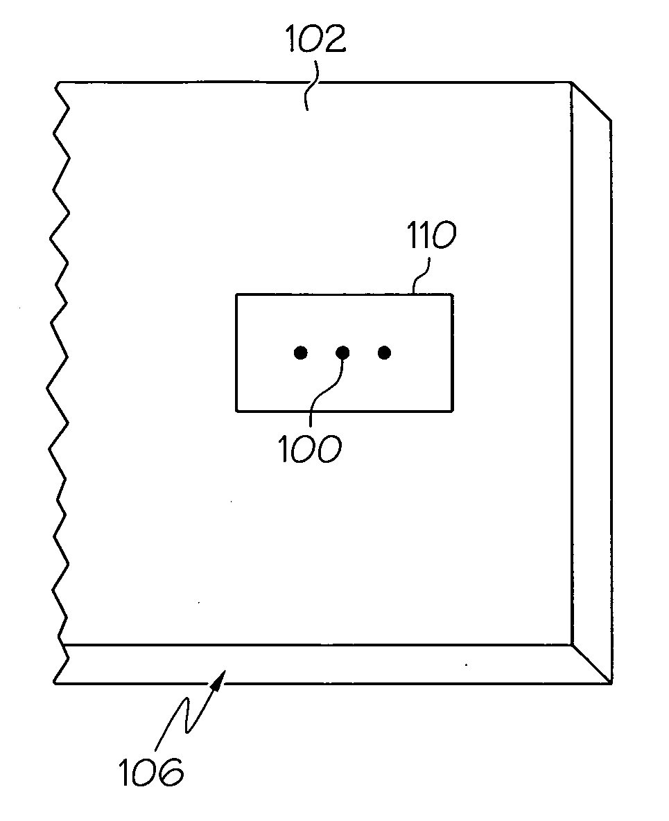
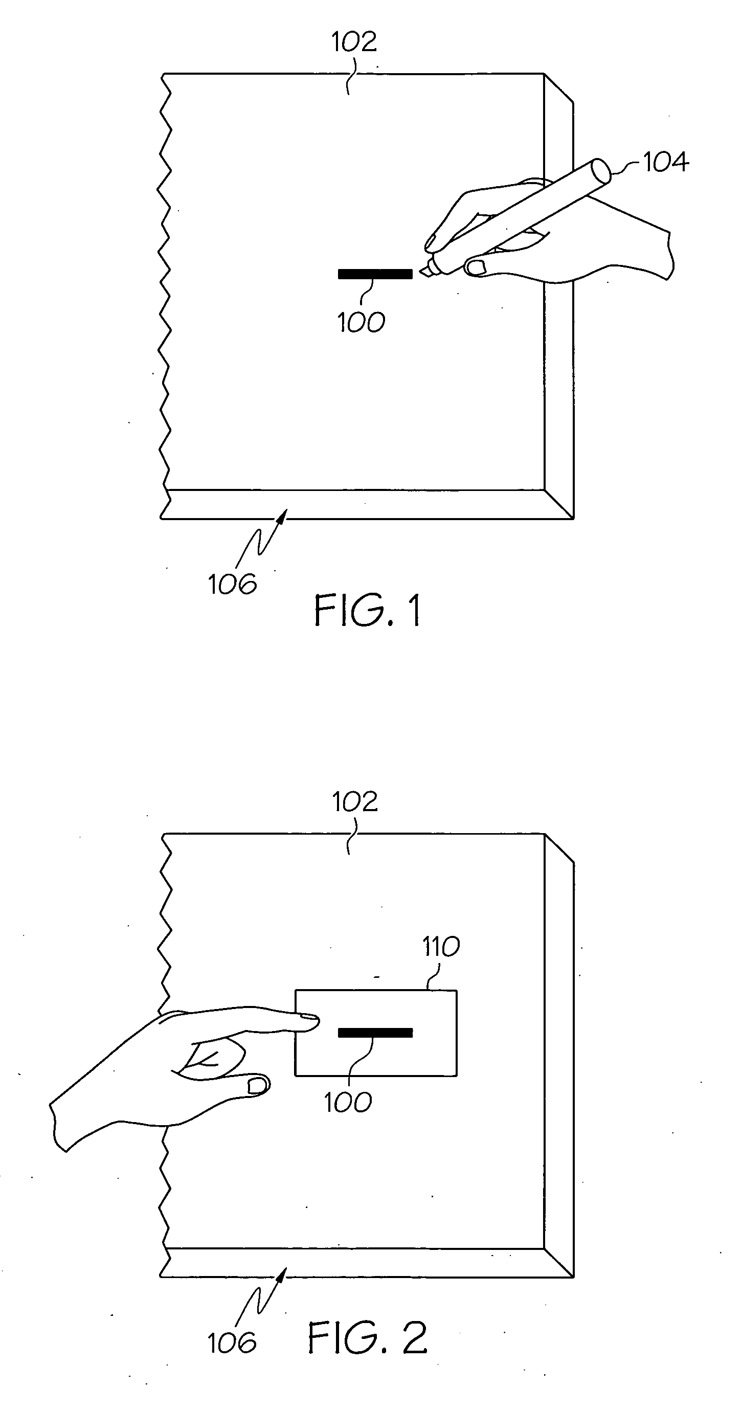
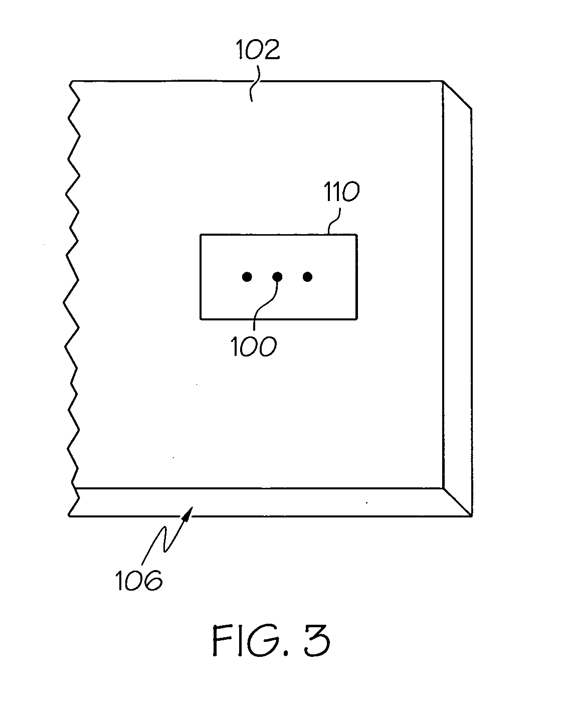
[0015]Surface temperature sensing is desirable in aircraft applications, and more particularly in the maintenance of aircraft line replaceable units (LRUs), such as a valve, actuator, portion of a turbine engine, or the like due to the deleterious effect high temperatures may have on these units; yet, it is also desirable that erroneous reporting be avoided to deter against unnecessary replacement costs.

[0016]Increased surface temperatures of aircraft LRUs are identified according to the present invention with temperature sensors that are manufactured to sense a pre-determined temperature dependent upon the LRU location in the aircraft. The ...


PUM

PropertyMeasurementUnit
temperaturesaaaaaaaaaa
sensing temperaturesaaaaaaaaaa
temperatureaaaaaaaaaa

Abstract

A method of sensing high surface temperatures in aircraft applications is provided. The method includes the steps of applying a temperature indicator material on a surface an object in which monitoring exposure to high temperatures is sought. The temperature indicator material is reactive to a pre-determined temperature threshold. The temperature indicator material is next covered with a heat resistant film to protect the material during exposure to operating temperatures and deleterious environmental conditions. An identified visible change in the temperature indicator material provides confirmation of exposure of the surface of the object to temperatures in excess of the pre-determined temperature threshold.

Description

FIELD OF THE INVENTION[0001]The present invention generally relates to temperature sensing and, more particularly, to a method of sensing high surface temperatures in aircraft applications.BACKGROUND OF THE INVENTION[0002]Many types of temperature sensors are known for indicating or detecting the presence of elevated temperatures on the surface of an object. One such type of sensor is a temperature indicator in the form of a label that includes a layer of material that changes its visible appearance at a pre-determined temperature. The layer of material, also referred to as indicating material, is typically provided on a piece of transparent or translucent foil. The usual arrangement is for the layer of indicating material and a layer of adhesive to be formed on the under-side of the foil during fabrication. In many cases, an optional printed layer is formed on an upper-side of the foil. During use, the foil is adhered to the surface of an object with the layer of indicating materia...

Claims


Application Information

Patent Timeline
Patent Type & Authority Applications(United States)
IPC IPC(8): G01K11/18G01K11/12
CPCC09D5/26G01K11/12G01K1/14
Inventor PLEVICH, CHARLES W.FOULK, DENNIS L.POLEC, THOMAS W.
Owner HONEYWELL INT INC
Why Eureka
Try Eureka