
Machining center

a technology of machining center and tool magazine, which is applied in the field of machine tools, can solve the problems of limited space for installing the machining center, limited number of tools, and limited storage of tools, and achieve the effect of increasing the installation spa

Inactive Publication Date: 2008-06-19
NISSHINBO IND INC
View PDF1 Cites 9 Cited by
  • Summary
  • Abstract
  • Description
  • Claims
  • Application Information

AI Technical Summary

Benefits of technology

[0018]The present invention provides a machining center capable of containing a large number of tools without the need for increased installation space, and further, provides a machining center that enables confirmation of whether or not an operator has mounted tools correctly in tool pockets of a tool magazine of the machining center to be carried out simply and easily.
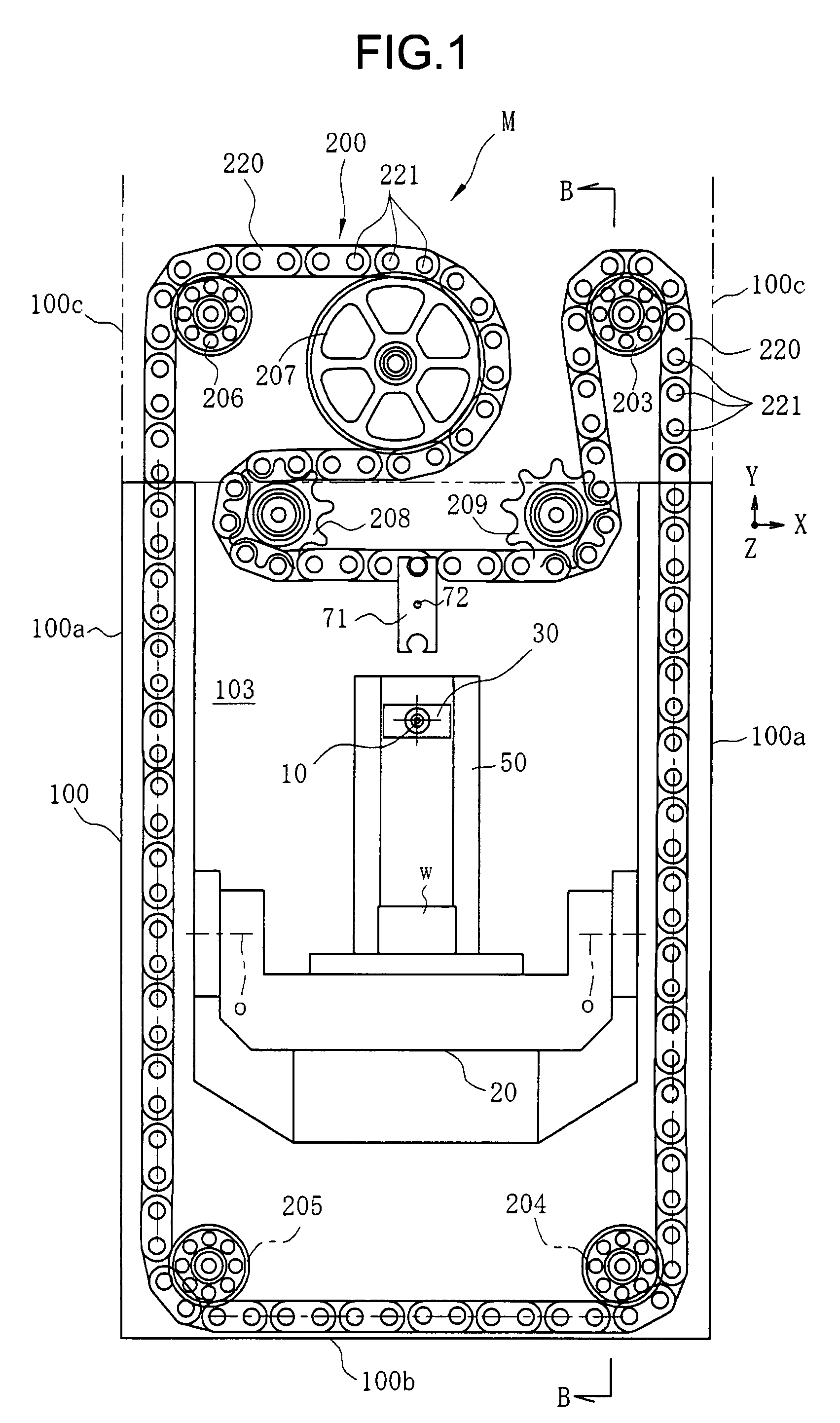
[0022]According to the present invention, no part of the tool magazine protrudes beyond the outside surface of the machining center, thereby enabling a large number of tools to be mounted in the tool magazine without increasing the installation space of the machining center.
[0023]In addition, preferably, the endless chain of the tool magazine is disposed adjacent to an inner wall surface and / or an outer wall surface of the machine frame or the machine cover over at least half its length, thereby enabling the number of tools that the tool magazine can store to be maximized without the need for more space.
[0024]Moreover, by using at least two drive components to drive the endless chain in a circulating manner, the tool magazine can be circulated smoothly. Having the automatic tool changer change the tool at a position between the two sprockets ensures that the tool change position remains constant even when the endless chain slackens.
[0025]Additionally, when an operator replaces the tools in the tool pockets of the tool magazine, the following procedure is used: First, the cover over the opening provided in the machine frame or the machine cover is opened. Then, the tool mounted in the tool pocket is removed and a new tool mounted. There is an engaged part located at the same position on every tool, and there is an engaging part provided on the cover that closes the opening. The engaging part engaging the engaged part enables the cover to close the opening, and the closing of the cover can be detected by the sensor. Therefore, the present invention makes it possible to confirm easily that the tool has been mounted properly using the simple structure described above.
[0026]Further, where the tool magazine is disposed so as to be contained within the machine frame of the machining center, the need for additional safety components such as a safety cover for the tool magazine can be minimized.

Problems solved by technology

However, there are problems with each of the three inventions described above.
Consequently, where space to install the machining center is limited, so too is the number of tools that can be stored.
But such a configuration severely limits the number of tools that can be stored in the magazine, making it difficult to cope with the variety of machining operations ordinarily performed by the machining center.
However, in the case of a small machining center this configuration limits the number of tools that can be stored in the tool magazine.
If a large number of tools is then stored in the tool magazine to achieve a variety of different types of machining the size of the tool magazine increases, making it difficult to achieve savings in the space required for the machining center.
Moreover, such a configuration requires that replacement of the tools in the tool magazine by an operator take place above head level, which is neither easy nor safe.

Method used


Image

  • Machining center
  • Machining center
  • Machining center

Examples


Embodiment Construction

[0036]A detailed description will now be given of illustrative embodiments of the present invention, with reference to the accompanying drawings. In so doing, although specific terminology is employed for the sake of clarity, the present disclosure is not to be limited to the specific terminology so selected, and it is to be understood that each specific element includes all technical equivalents that operate in a similar manner and achieve a similar result.

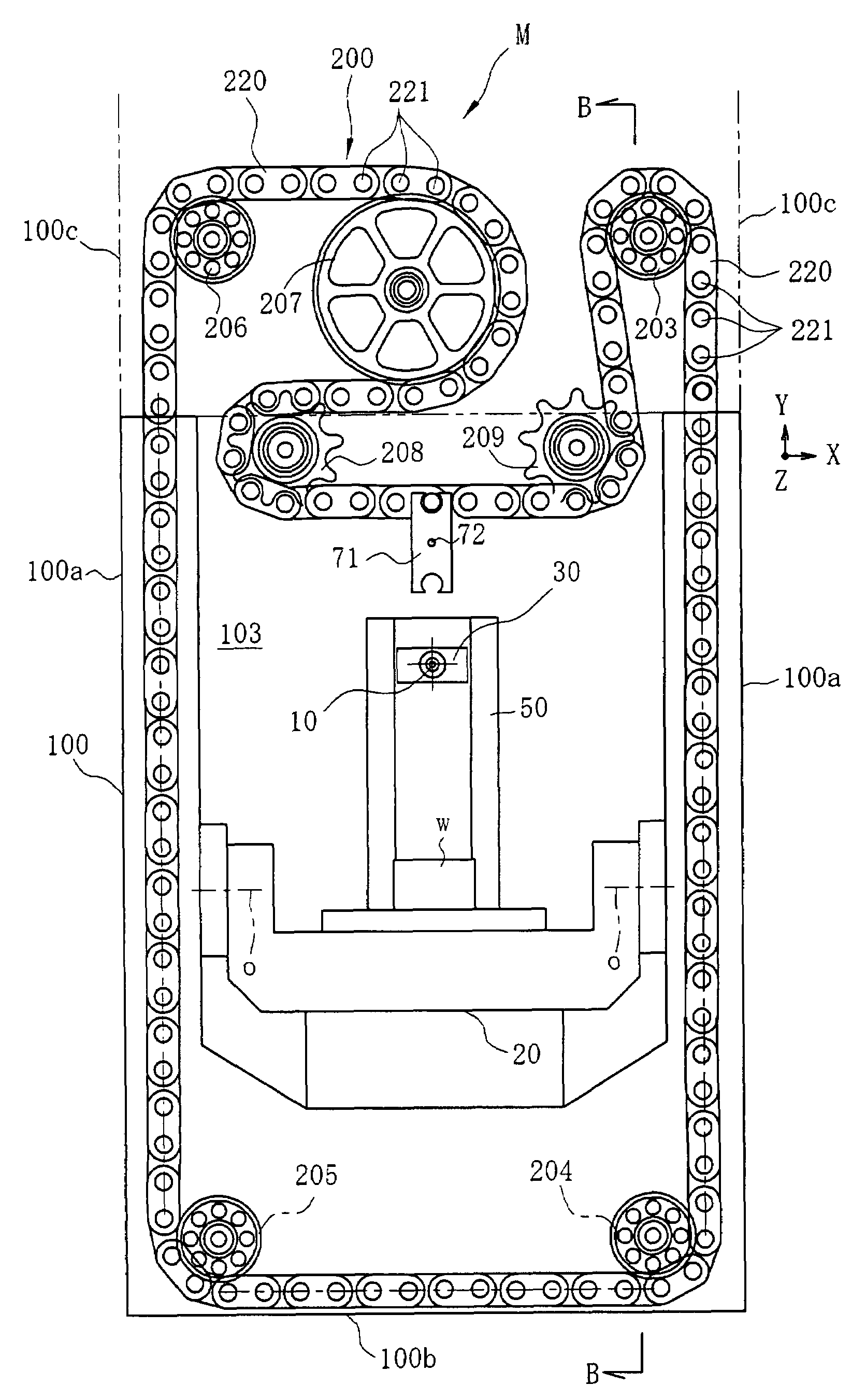
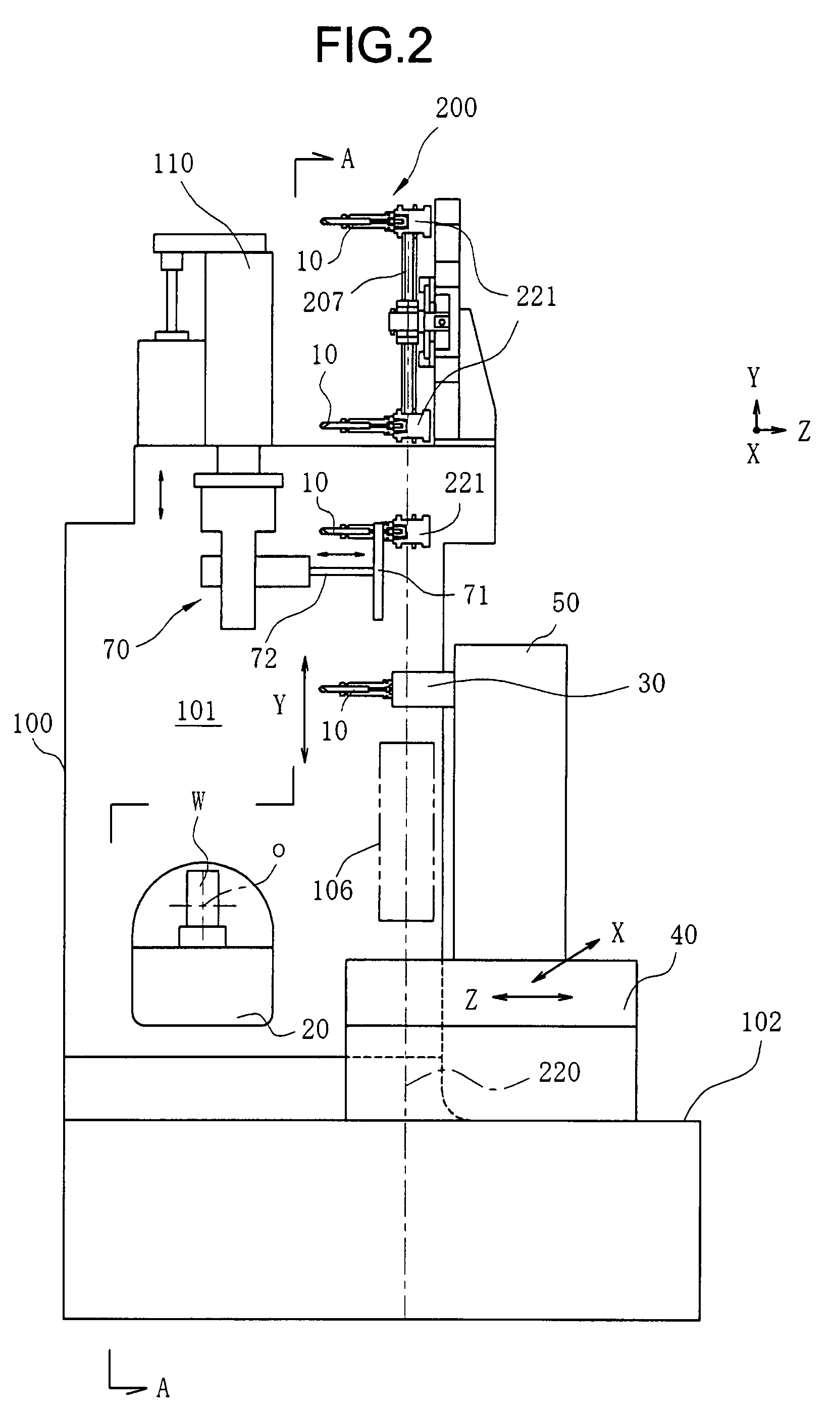
[0037]Referring now to the drawings, in particular FIGS. 1 and 2, first, a description is given of embodiments of the present invention using an example of a configuration in which a tool magazine is disposed inside of an outer side surface of a machining center or an extension surface thereof at a side portion of the machining center.

[0038]FIGS. 1 and 2 show schematically the machining center according to one embodiment of the present invention, in which FIG. 1 shows a view along a line A-A shown in FIG. 2 and FIG. 2 shows a vie...


PUM


Abstract

A machining center includes a tool magazine having an endless chain to hold multiple tool pockets, a spindle to which a tool that performs a machining operation on a workpiece may be detachably attached, and an automatic tool changer to change the tool disposed between the tool pockets and the spindle. A portion of the tool magazine disposed opposite a machine frame of the machining center or a machine cover of the machining center is disposed adjacent to a side surface and a bottom surface of the machine frame or the machine cover.

Description

CROSS-REFERENCE TO RELATED APPLICATIONS[0001]The present specification claims priority from Japanese Patent Application No. 2006-340637, filed on Dec. 19, 2006 in the Japan Patent Office, the entire contents of which are hereby incorporated by reference herein.BACKGROUND[0002]1. Field of the Invention[0003]The present invention relates to a machine tool such as a machining center, and more particularly, to a machining center equipped with a tool magazine for automatic tool exchange.[0004]2. Description of the Background Art[0005]A machining center is equipped with a tool magazine containing a variety of tools to enable a wide variety of machining operations to be carried out with a single machine. A tool stored in the tool magazine and a tool mounted on a spindle are exchanged by an automatic tool changer controlled by a controller to enable a wide variety of machining operations to be carried out.[0006]Conventionally, three main types of automatic tool changing methods as described...

Claims


Application Information

Patent Timeline
Patent Type & Authority Applications(United States)
IPC IPC(8): B23Q3/157
CPCB23Q3/15526B23Q3/15766Y10T483/115Y10T483/13Y10T483/1891B23Q3/15724B23Q3/15713B23Q11/08B23Q17/007
Inventor ISHIKAWA, AKIHIKOFUJITANI, TAKUJI
Owner NISSHINBO IND INC
Learn More