

Electrocautery system, provided with safe lighting during operational use
- Summary
- Abstract
- Description
- Claims
- Application Information
AI Technical Summary
Benefits of technology
Problems solved by technology
Method used
Image

Examples
Embodiment Construction
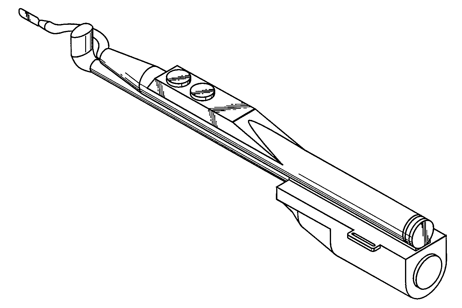
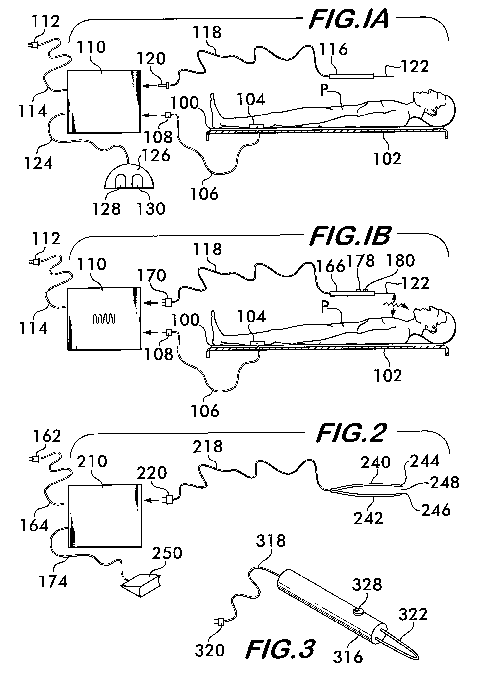
[0040]As best understood with reference to FIG. 1A, in a conventional arrangement for monopolar cauterization of a patient's tissue the patient “P” is placed on an electrically insulated surface 100 of an operating table 102. The patient is placed in contact with an electrically conductive contact pad 104 connected to a conductor 106, generally referred to as an electrical ground, which typically has a plug 108 at a distal end. The system has a control unit 110 that can be plugged into an electrical power source (not shown, but usually an a.c. mains socket) via plug 112 to receive an electric power flow, e.g., at 110V at 50 cps, via cable 114. Suitable circuitry of known kind (not shown), usually mostly accommodated in control unit 110, modifies the received current and voltage as appropriate. Control unit 110 has an output socket (not shown) into which a user can plug in a handpiece 116 via a cable 118 and plug 120. Handpiece 116 in such a system may have no additional controls, bu...
PUM
 Abstract
Description
Claims
Application Information