Bilayer patch device for hernia repair

a patch device and hernia technology, applied in the field of hernia repair, can solve the problems of patch position change, double-layer design cannot be evenly attached to the peritoneum cavity,

Inactive Publication Date: 2008-06-19
UEN YIH HUEI
View PDF2 Cites 36 Cited by
  • Summary
  • Abstract
  • Description
  • Claims
  • Application Information

AI Technical Summary

Benefits of technology

[0005]It is the primary objective of the present invention to provide a bilayer patch devic

Problems solved by technology

However, this double-layer design can not be attached to the peritoneum cavity evenly because the pa

Method used


Image

  • Bilayer patch device for hernia repair
  • Bilayer patch device for hernia repair
  • Bilayer patch device for hernia repair

Examples


first embodiment

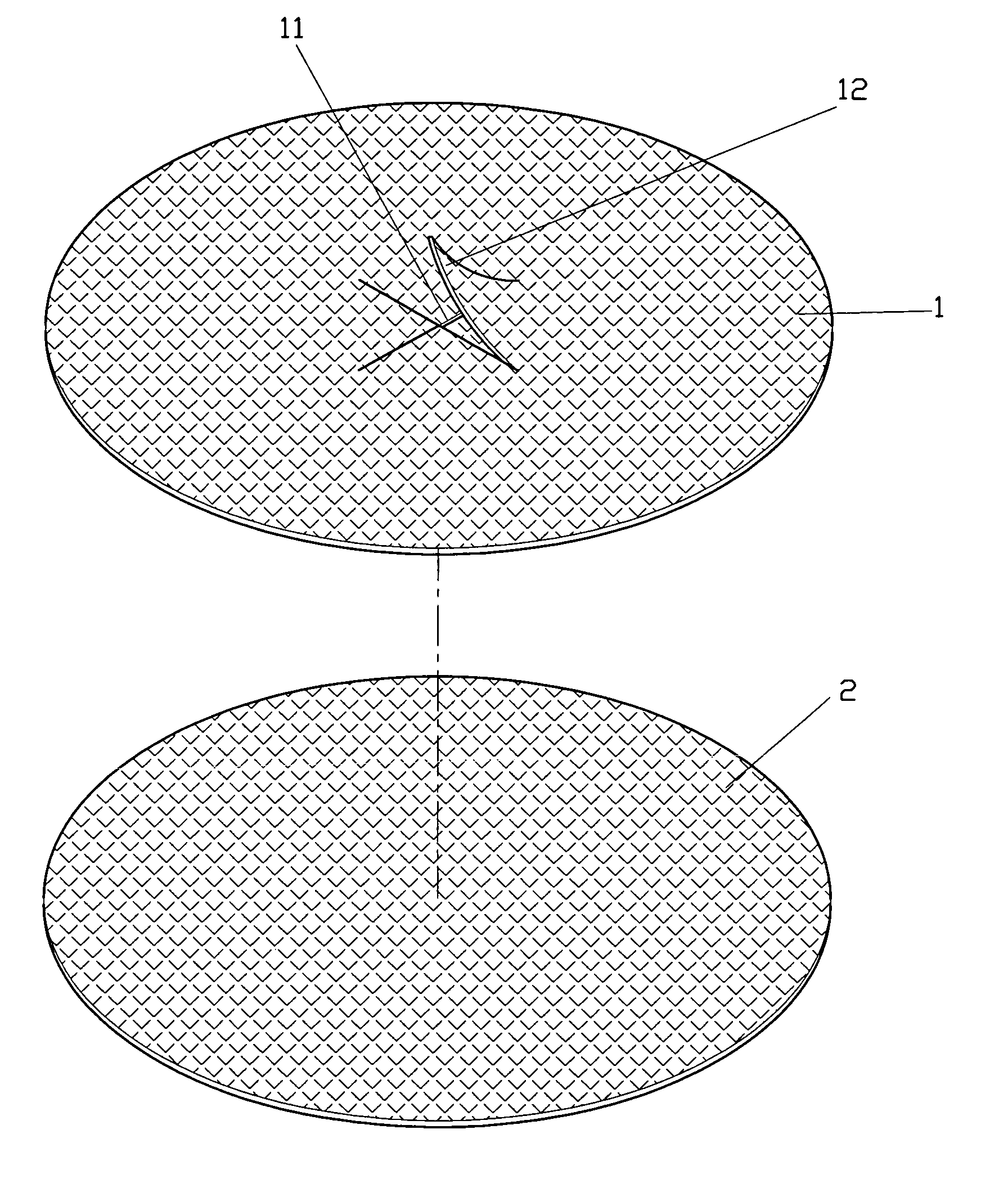
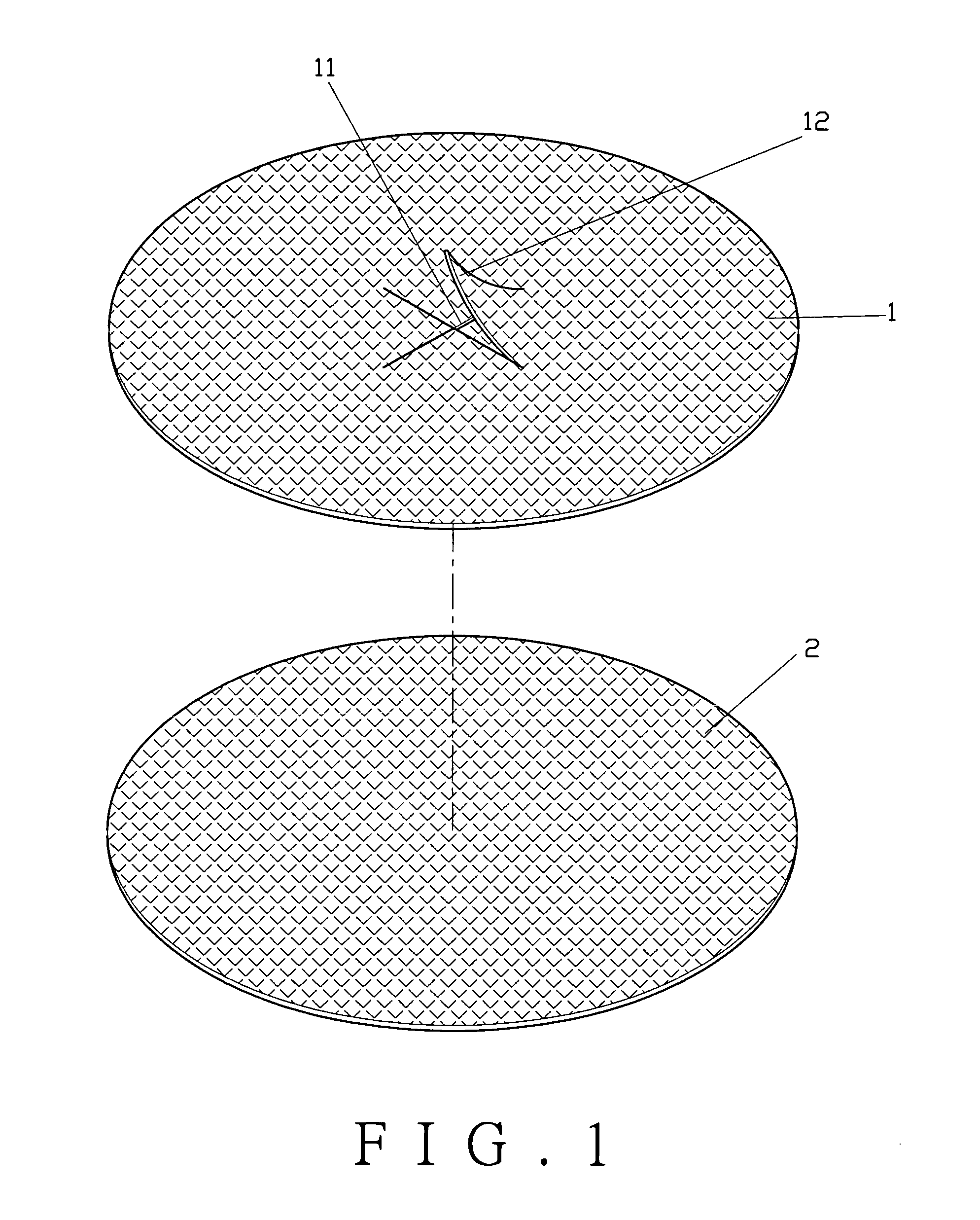
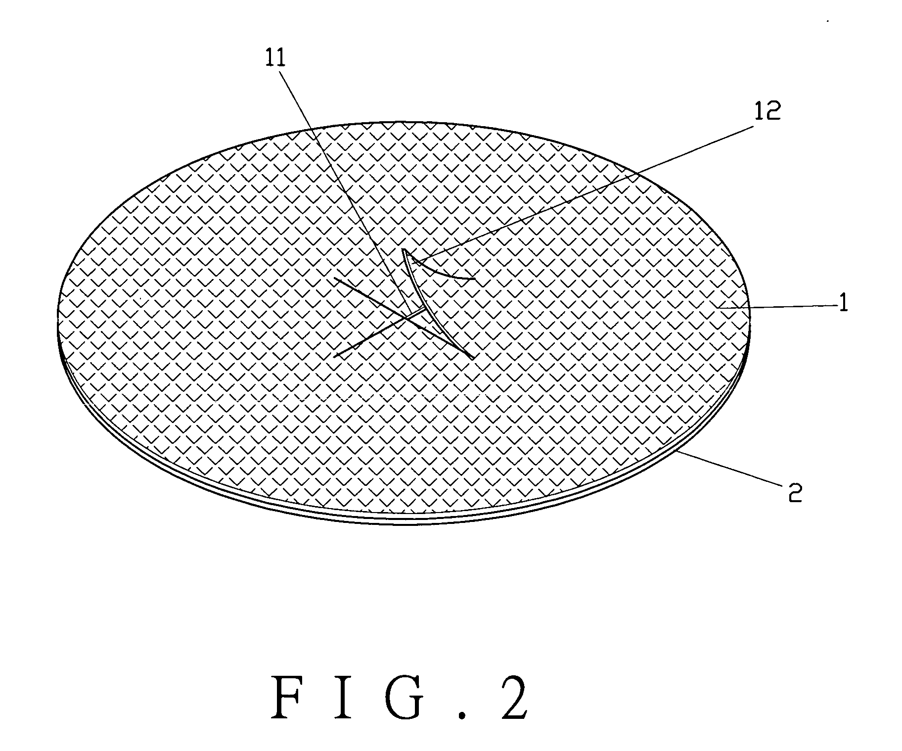
[0019]As shown in FIGS. 1 to 3, a bilayer patch device for hernia repair of the present invention comprises a first layer 1 and a second layer 2.

[0020]The first layer 1 is cut to form locating flakes 12 by cutting lines 11. In this embodiment, the four cutting lines 11 are connected to a center point to form the four locating flakes 12. The four locating flakes 12 are opened to form an opening. This embodiment may use two, three or five cutting lines 11. All of the cutting lines 11 are connected at a common point.

[0021]The second layer 2 has its edge connected with the edge of the first layer 1 to form a pocket. The connecting edges of the first layer 1 and the second layer 2 are connected with threads, glue or using high wave frequency method.

[0022]In practice the first embodiment of the present invention, as shown in FIGS. 4 and 5, the bilayer patch device of the present invention is placed into a cavity 31 of the patient's peritoneum 3 with locating threads 4 inserted through the...

second embodiment

[0023]As shown in FIGS. 6 and 7, the present invention comprises a first layer 1A having cutting lines 11A thereon to form locating flakes 12A. A second layer 2A has its edge connected with the edge of the first layer 1A to form a pocket. The second layer 2A further comprises an auxiliary layer 21A on the top of the second layer 2A to be inserted through the locating flakes 12A of the first layer 1A. The auxiliary layer 21A is in a shallow barrel. An open end is formed between the auxiliary layer 21A and the locating flakes 12A.

third embodiment

[0024]As shown in FIGS. 8 and 9, the present invention comprises a first layer 1B having cutting lines 11B thereon to form locating flakes 12B. A second layer 2B has its edge connected with the edge of the first layer 1B to form a pocket. The second layer 2A further comprises an auxiliary layer 21B on the top thereof. The auxiliary layer 21B comprises a fin 22B to be inserted through the locating flakes 12B of the first layer 1B. The auxiliary layer 21B is in a shallow barrel. The fin 22B facilitates the user's operation. An open end is formed between the auxiliary layer 21B and the locating flakes 12B.


PUM


Abstract

A bilayer patch device for hernia repair includes a first layer and a second layer. The first layer is cut to form locating flakes by cutting lines. The edges of the first layer and the second layer are connected to form a pocket. The second layer further comprises an auxiliary layer. The auxiliary layer further comprises a fin thereof. The patch is able to be flat attached to a cavity of the peritoneum for repairing a hernia.

Description

BACKGROUND OF THE INVENTION[0001]1. Field of the Invention[0002]The present invention relates to a bilayer patch device for hernia repair, in particular to a flat pocket-shaped patch which is able to be attached to a peritoneum cavity of the patient to increase the quality of hernia repair and to avoid recurrence of the hernia.[0003]2. Description of the Prior Art[0004]A conventional patch device for hernia repair, as described in the U.S. Pat. No. 6,241,768, uses a double-layer in a flat shape design, which made improvement with respect to a single-layer patch. However, this double-layer design can not be attached to the peritoneum cavity evenly because the patch can not be fixed to the cavity of the peritoneum. When the internal organs squirm, the patch moves along with the internal organs. That may cause the patch to change its position.SUMMARY OF THE INVENTION[0005]It is the primary objective of the present invention to provide a bilayer patch device for hernia repair, which can...

Claims


Application Information

Patent Timeline
IPC IPC(8): A61B17/08
CPCA61F2/0063
Inventor UEN, YIH-HUEI
Owner UEN YIH HUEI
Why Eureka
Try Eureka