Closing Device

a technology of sealing device and sealing valve, which is applied in the direction of valve housing, packaging goods type, braking system, etc., can solve the problems of disadvantageous disclosure sealing concept, and achieve the effects of less expensive and safe manufacture, generous tolerance in manufacturing and assembly, and free from damag

Active Publication Date: 2008-06-26
CONTINENTAL TEVES AG & CO OHG
View PDF9 Cites 4 Cited by
  • Summary
  • Abstract
  • Description
  • Claims
  • Application Information

AI Technical Summary

Benefits of technology

[0006]In view of the above, an object of the invention is to provide a closing device of the type initially referred to, which is characterized by a simplified, less expensive and safe manufacture, and special importance is attached to an assembly that offers a mix-up prevention and is free from damage, while allowing generous tolerances in terms of manufacture and assembly.

Problems solved by technology

The disclosed sealing concept is considered as disadvantageous in view of the many steps of machining and assembling needed.

Method used


Image

  • Closing Device
  • Closing Device

Examples


Embodiment Construction

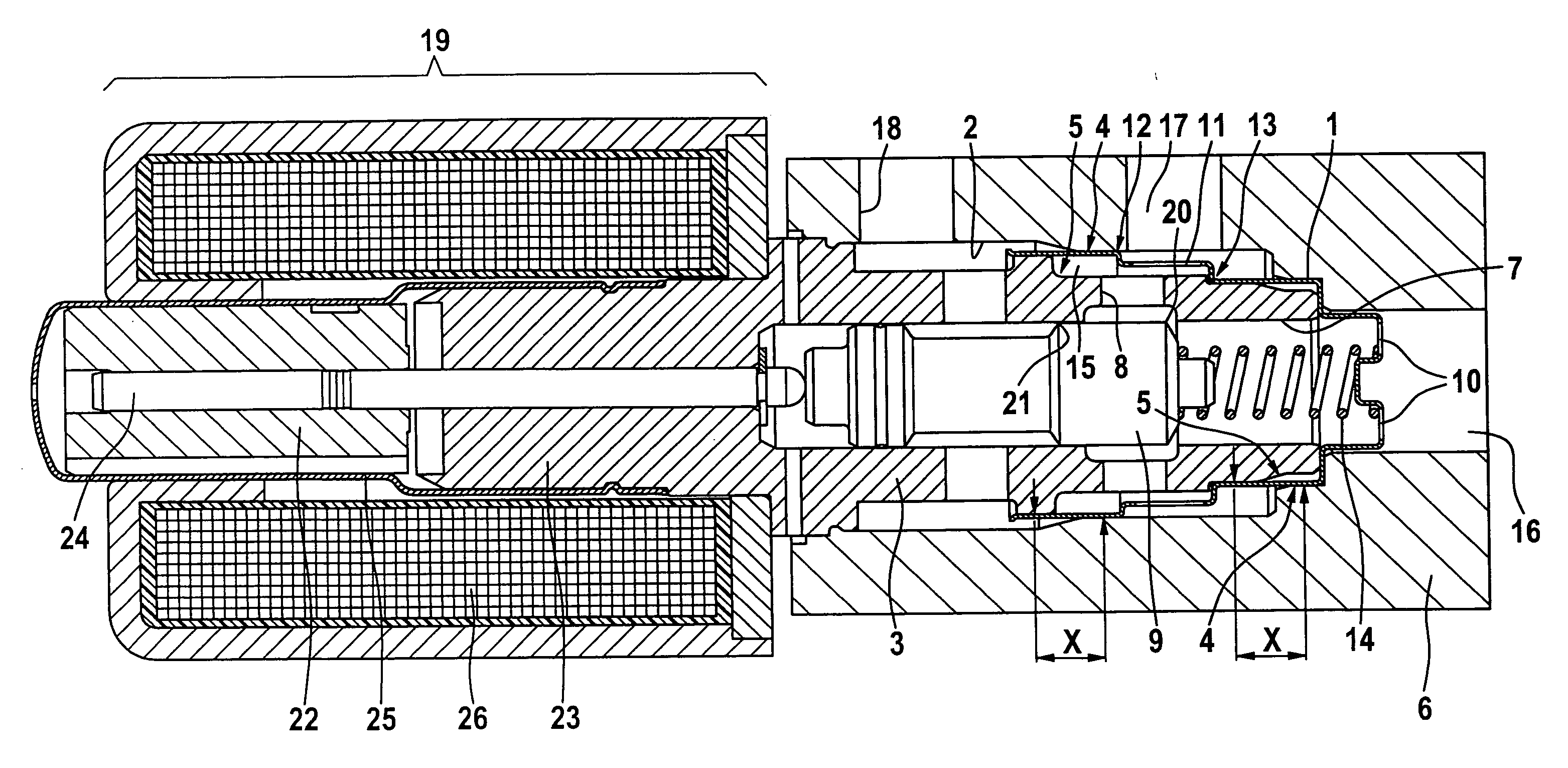
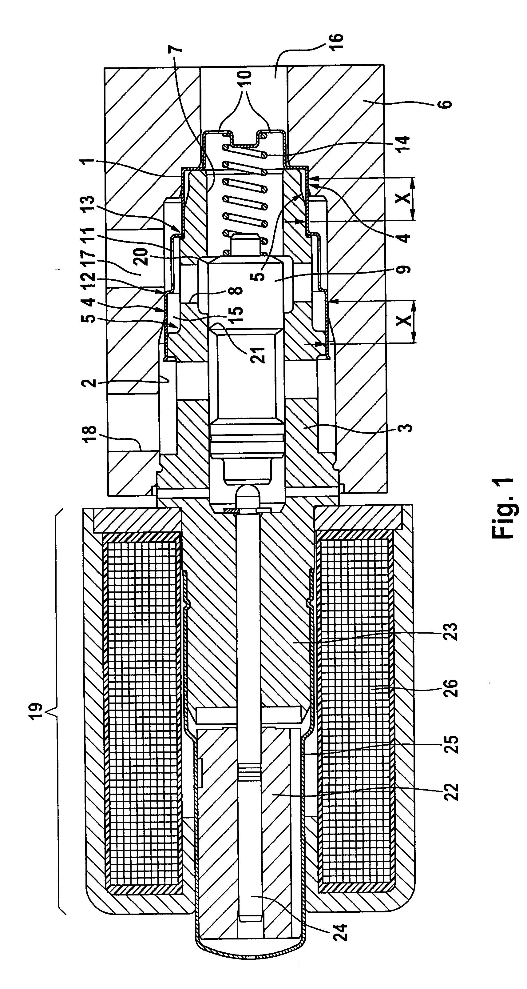
[0010]FIG. 1 shows a longitudinal cross-sectional view of the closing device of the invention for closing pressure-fluid-conveying channels 16, 17, 18 in a housing 6, into which a cartridge-type closing member 3 is mounted in a pressure-fluid tight fashion. To seal the closing member 3 in an accommodating bore 2 of the housing 5 that is provided for the closing member 3, a sealing body is arranged between the closing member 3 and the accommodating bore 2, which is configured as a sleeve member 1 according to the invention, whose peripheral surface is arranged between the accommodating bore 2 and the closing member 3, and is subjected to a defined tolerance-compensating surface pressure in sections.

[0011]In the joining direction of the closing member 3, both the accommodating bore 2 and the closing member 3 are respectively provided with a pair of stepped portions 4, 5 decreasing in diameter. Provided between the stepped portions 5 of the closing member 3 and the stepped portions 4 o...


PUM

PropertyMeasurementUnit
pressureaaaaaaaaaa
surface pressureaaaaaaaaaa
diameteraaaaaaaaaa

Abstract

A closing device for closing channels in which pressure fluid is conveyed in a housing. The closing device includes a sealing body that is designed as a sleeve member, the peripheral surface of which is arranged between the accommodating bore and the closing member for sealing purposes, and is subjected to a defined surface pressure in sections.

Description

[0001]This application is the U.S. national phase application of PCT International Application No. PCT / EP2006 / 050066, filed Jan. 6, 2006, which claims priority to German Patent Application No. DE102005004679.7, filed Feb. 2, 2005 and German Patent Application No. DE102005034985.4, filed Jul. 27, 2005, the contents of such applications being incorporated by reference herein.BACKGROUND OF THE INVENTION[0002]1. Field of the Invention[0003]The present invention relates to a closing device for closing channels in a housing in which pressure fluid is conveyed according to the preamble of patent claim 1.[0004]2. Description of the Related Art[0005]DE 196 43 289 A1 discloses a closing device of this type, for example. The closing device consists of a cartridge-like closing member, which is mounted into an accommodating bore of a housing in a pressure-fluid tight relationship thereto, with several elastic sealing rings being arranged in circumferential grooves of the closing member for seali...

Claims


Application Information

Patent Timeline
Patent Type & Authority Applications(United States)
IPC IPC(8): B65B1/00
CPCF16K27/041B60T8/3665F16K27/048F16K31/0613Y10T137/86622Y10T137/86686Y10T137/8671
Inventor VOSS, CHRISTOPHCOURTH, CHRISTIAN
Owner CONTINENTAL TEVES AG & CO OHG
Why Eureka
Try Eureka