Combination Capacitive Proximity Sensor and Ultrasonic Sensor for Material Level Monitoring

Inactive Publication Date: 2008-06-26
THE GSI GRP LLC
View PDF15 Cites 5 Cited by
  • Summary
  • Abstract
  • Description
  • Claims
  • Application Information

AI Technical Summary

Benefits of technology

[0006]An advantage of the present invention is a continuous ultrasonic level detector that is accurate and reliable.
[0007]Another advantage is the use of an inexpensive and durable capacitive proximity sensor to detect material levels proximate or within the dead zone of the ultrasonic sensor.
[0008]Another advantage is a material level sensor that provides a single accurate level detection output s

Problems solved by technology

Mechanical or electromechanical devices can be useful in liquids but are not reliable when dealing with particulate solids such as powders, grains, feed, and the like.
Reflected ultrasound cannot be accurately measured until the piezo-crystal stops vibrating.
In addition, the ultrasonic sensor may indicate a false level under these conditions.
In bins or silos where accurate estimates of material levels are essential to monitor inventory and/or consumption, ultrasonic sensors are not useful.
For example, in bins or silos th

Method used


Image

  • Combination Capacitive Proximity Sensor and Ultrasonic Sensor for Material Level Monitoring
  • Combination Capacitive Proximity Sensor and Ultrasonic Sensor for Material Level Monitoring
  • Combination Capacitive Proximity Sensor and Ultrasonic Sensor for Material Level Monitoring

Examples


Embodiment Construction

[0015]While the following description details the preferred embodiments of the present invention, it is to be understood that the invention is not limited in its application to the details of construction and arrangement of the parts illustrated in the accompanying drawings, since the invention is capable of other embodiments and of being practiced in various ways.

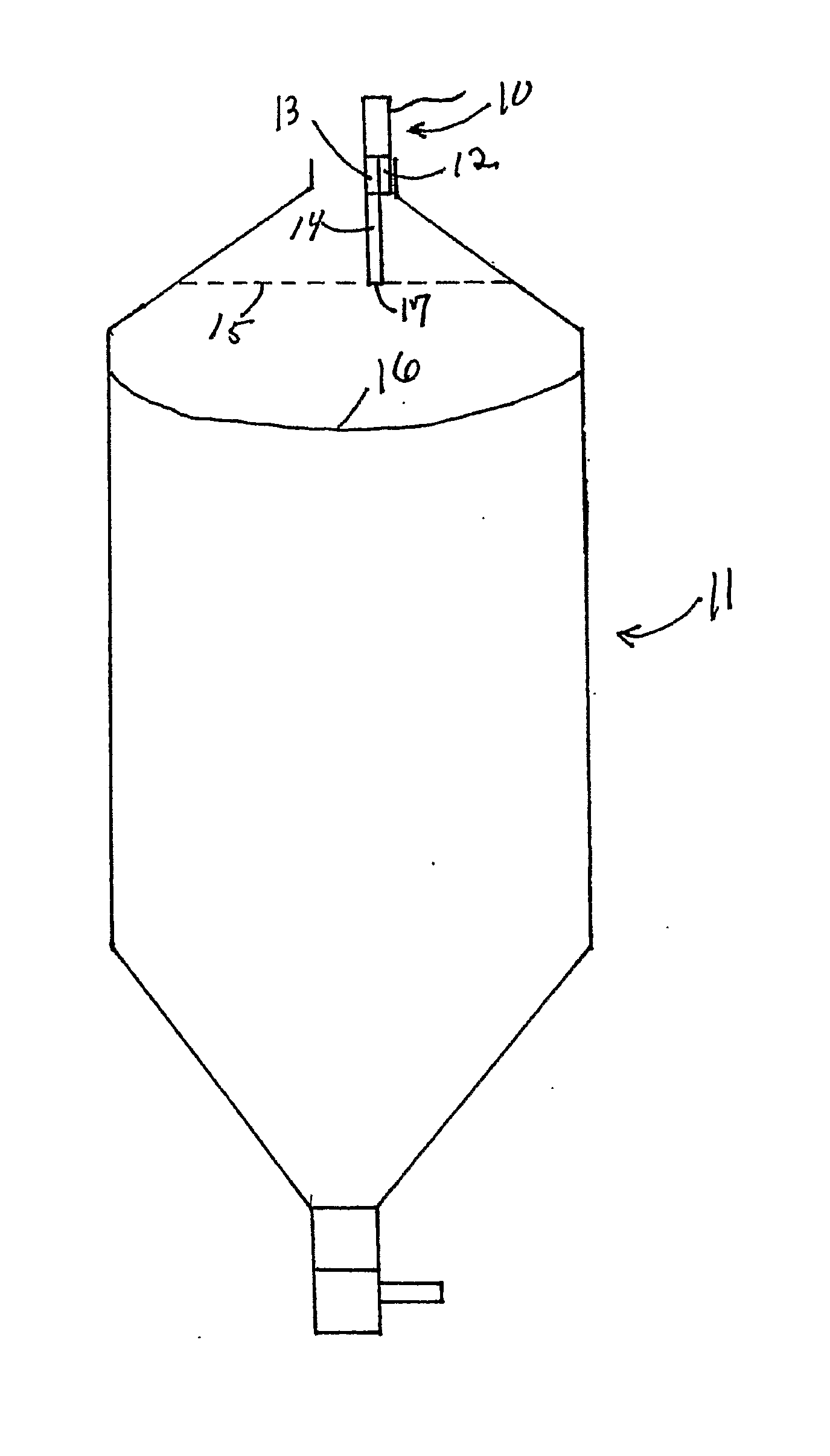
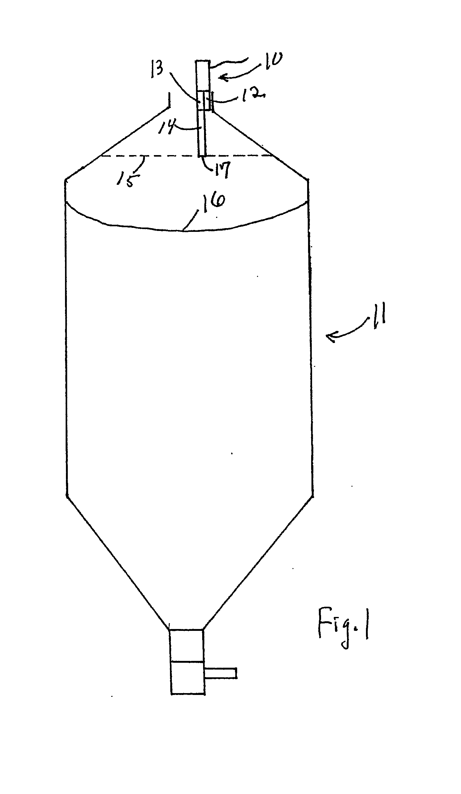
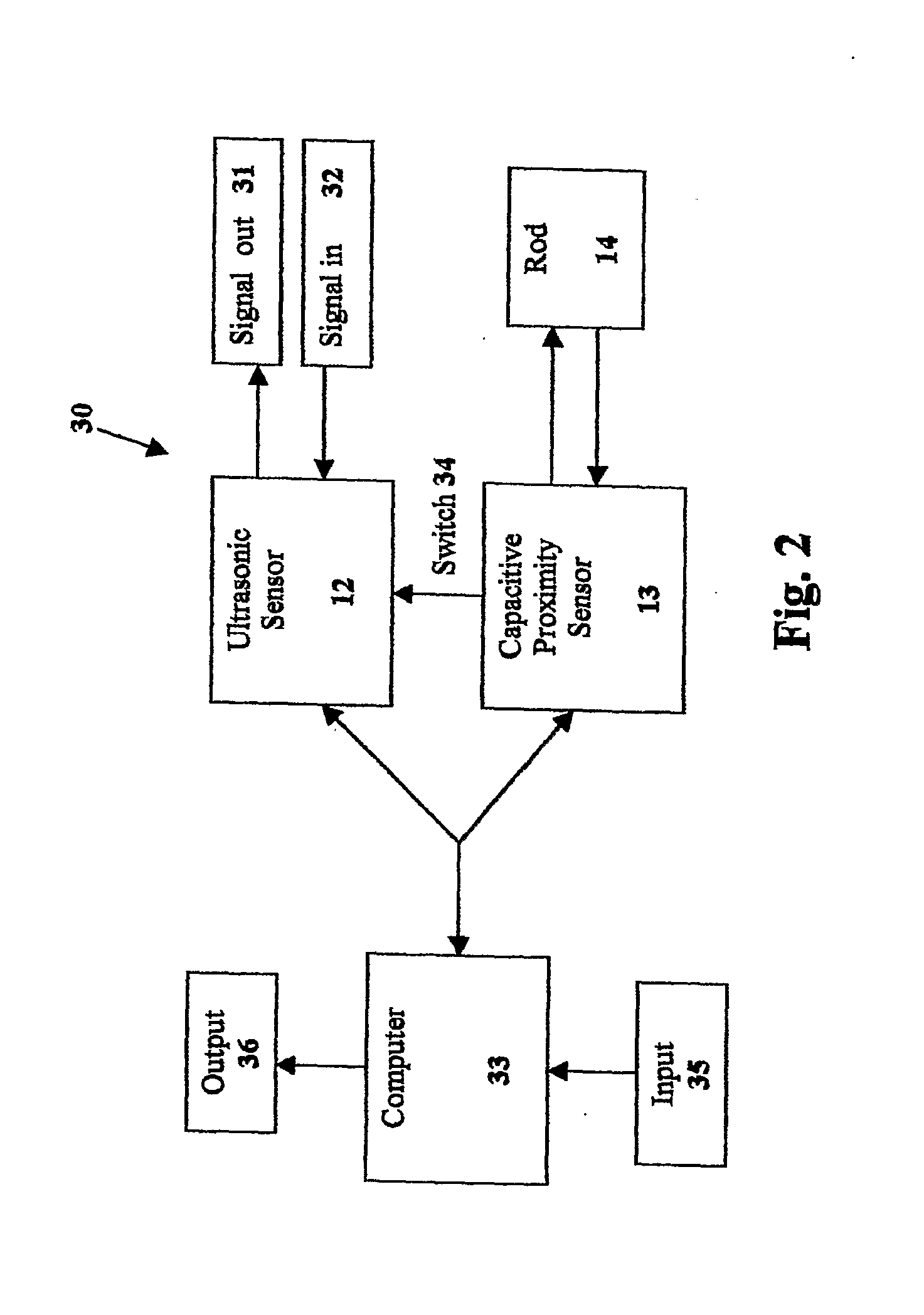
[0016]FIG. 1 shows the material level sensor 10 of the present invention in place at the top of a feed silo 11. Material level sensor 10 has a continuous ultrasonic sensor 12 and a capacitive proximity sensor 13. Capacitive proximity sensor 13 has a detecting rod 14 which extends downward to or beyond the limit of the dead zone 15 of ultrasonic sensor 12. Ultrasonic sensor 12 detects the level of feed material 16 in silo 11, and capacitive proximity sensor 13 detects the level at the tip 17 of rod 14, which may be, for example, at or just beyond the limit of the dead zone 14 of the ultrasonic sensor 12.

[0017]A capacitor co...


PUM


Abstract

A material level detection sensor (10) having a continuous ultrasonic sensor (12) and a capacitive proximity sensor (13). The capacitive proximity sensor detects the material only when the material is at or within the dead zone (15) of the ultrasonic sensor, at which point it switches the ultrasonic sensor off. The ultrasonic sensor transmits a level detection output signal until it is turned off by the capacitive proximity sensor. The capacitive proximity sensor transmits a level detection output signal only when it detects the material, and it will switch the ultrasonic sensor on when it does not detect the material. The material level detection sensor transmits only a single level detection output signal at any given time, providing an accurate and reliable estimate of material level. The device is particularly useful for measuring inventory and consumption of particulate solids and powders in bins or silos (11).

Description

TECHNICAL FIELD[0001]The present invention relates to material level sensors to gauge the level of material in containers and, more particularly, to a continuous level sensor that consists of an ultrasonic sensor and a capacitive proximity sensor wherein the capacitive proximity sensor shuts off the continuous ultrasonic sensor when the material being detected is within the dead zone area of detection of the ultrasonic sensor.BACKGROUND ART[0002]Numerous continuous level sensors have been devised to detect the level of liquid or solid particulate matter in bins or silos. Mechanical or electromechanical devices can be useful in liquids but are not reliable when dealing with particulate solids such as powders, grains, feed, and the like. Other sensors include ultrasonic, radar, and time, domain reflectometry. The ultrasonic sensor is popular because of its relative accuracy and simplicity of operation. The ultrasonic sensor is located at or near the top of a container and transmits ul...

Claims


Application Information

Patent Timeline
IPC IPC(8): G01F23/26
CPCG01F23/2962G01F23/265
Inventor CRIDER, BRETT
Owner THE GSI GRP LLC
Why Eureka
Try Eureka