Method of Using a Bullet Proof Vest

a technology of bulletproof vest and bulletproof shell, which is applied in the field of bulletproof vest, can solve the problems of increasing the risk of injury to the wearer of the bulletproof vest, heavy weight and uncomfortable use of such vests, and increasing the risk of bulletproof vest wear, so as to increase the volume of the enclosure, increase the pressure inside the airtight enclosure, and ensure the safe reception of bullets.

Inactive Publication Date: 2008-06-26
GRAPHENIUS JONAS
View PDF16 Cites 16 Cited by
  • Summary
  • Abstract
  • Description
  • Claims
  • Application Information

AI Technical Summary

Benefits of technology

[0003]The bullet proof vest of the present invention provides a solution to the above-mentioned problems. The method of the present invention is for safely receiving a bullet in a bullet proof vest. A plate structure is provided that has an airtight enclosure enclosing high performance fiber layers, a hard layer, a textile layer having openings defined therein and a semi-solid and sticky layer such as bitumen or rubber. A bullet may penetrate through the airtight enclosure. The pressure inside the airtight enclosure is increased as a result of the energy and heat of the bullet. The increased pressure increases the volume of the enclosure and separates the layers from the hard layer and the textile layer from the hard layer. The hard layer may be used to deform the bullet. The textile layer attaches to the bullet to follow the bullet as the bullet moves into the rubber layer. The semi-solid sticky layer sticks to the bullet as the bullet penetrates through the plate structure to further slow down the bullet. An air-bubble layer may transversely distribute the bullet impact. The vest of the present invention has convenient snap-on fasteners that make it easy to take on and take off the vest and to remove and insert the removable plates. More particularly, the vest has pockets defined therein so that the user may remove the plates and replace the plates with different plates by inserting the different plates into the pockets.

Problems solved by technology

However, many of such vests are heavy and uncomfortable to use.
Conventional vests are often not as reliable when many shots are fired into them and the risk of injury to the wearer of the bullet proof vest increases.

Method used


Image

  • Method of Using a Bullet Proof Vest
  • Method of Using a Bullet Proof Vest
  • Method of Using a Bullet Proof Vest

Examples


Embodiment Construction

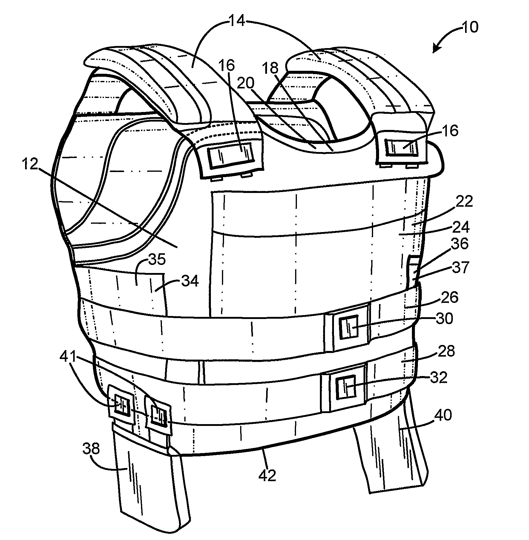
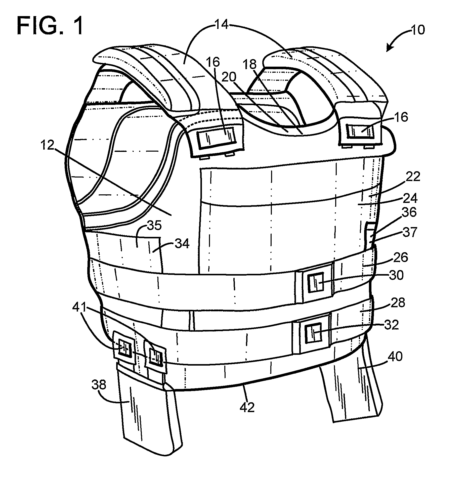
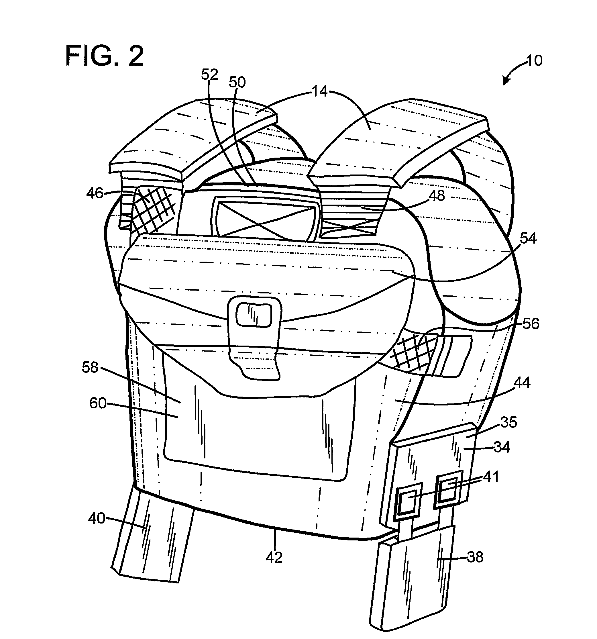
[0008]FIGS. 1-2 show a bullet proof vest 10 of the present invention that has a front body armor section 12 with shoulder straps 14 that have snap fasteners 16 for easy take off and fastening of the vest 10. The front section 12 has an openable inside pocket 18 defined therein that extends across the entire front section 12. The pocket 18 has an armor plate 20 disposed therein to provide bullet protection for the entire front page of the body of the wearer. The section 12 has an openable outside pocket 22 defined therein for holding an additional armor plate 24.

[0009]Straps 26, 28 enclose the vest 10. The straps 26, 28 have snap fasteners 30, 32 for easy take-on and take-off of the vest. Extra side plates 34, 36 may be disposed at the lower end of the vest in pockets 35, 37 to provide extra protection for the kidney and other vital organs of the wearer. Snap-on double side plates 38, 40 may extend downwardly or hang from a lower edge 42 of the vest to protect the hip area. The plate...


PUM

PropertyMeasurementUnit
pressureaaaaaaaaaa
volumeaaaaaaaaaa
structureaaaaaaaaaa

Abstract

The method is for receiving a bullet in a bullet proof vest. A plate structure is provided that has an airtight enclosure enclosing high performance fiber layers, a hard layer, a textile layer having openings defined therein and a semi-solid layer such as bitumen. A bullet penetrates through the airtight enclosure. The pressure inside the airtight enclosure is increased. The increased pressure separates the layers from the hard layer and the textile layer from the hard layer. The hard layer deforms the bullet. The textile layer attaches to the bullet to follow the bullet. The layer sticks to the bullet as the bullet penetrates through the plate structure.

Description

TECHNICAL FIELD[0001]The present invention relates to a bullet proof vest.BACKGROUND OF THE INVENTION[0002]Bullet proof vests have been used for a long time. However, many of such vests are heavy and uncomfortable to use. Conventional vests are often not as reliable when many shots are fired into them and the risk of injury to the wearer of the bullet proof vest increases. There is a need for a vest that protects against multiple bullets without overheating that reduces the protection. There is a need for a bullet proof vest that is comfortable and can handle a plurality of bullets without reduced protection provided by the vest. There is also a need for a vest that can easily be adjusted to the specific needs of the user so that more protection is provided in certain dangerous situations and less protection when there is less risk of being shot at with a heavy duty weapon.SUMMARY OF THE INVENTION[0003]The bullet proof vest of the present invention provides a solution to the above-m...

Claims


Application Information

Patent Timeline
Patent Type & Authority Applications(United States)
IPC IPC(8): F41H1/02
CPCF41H1/02F41H5/0478F41H5/0457
Inventor GRAPHENIUS, JONAS
Owner GRAPHENIUS JONAS
Why Eureka
Try Eureka