System and Method for Lubricating Power Transmitting Elements

Inactive Publication Date: 2008-06-26
KOHLER CO
View PDF10 Cites 10 Cited by
  • Summary
  • Abstract
  • Description
  • Claims
  • Application Information

AI Technical Summary

Benefits of technology

[0008]Advantageously, during engine operation, a constant or substantially supply of lubricating oil can be provid

Problems solved by technology

Without proper lubrication to flush away or otherwise remove contaminants, power transmitting elements in engines progressively wear during use.
Such wear results in decreased service life of a given piece of equipment.
However, during engine use, the slight relative movement b

Method used


Image

  • System and Method for Lubricating Power Transmitting Elements
  • System and Method for Lubricating Power Transmitting Elements
  • System and Method for Lubricating Power Transmitting Elements

Examples


Embodiment Construction

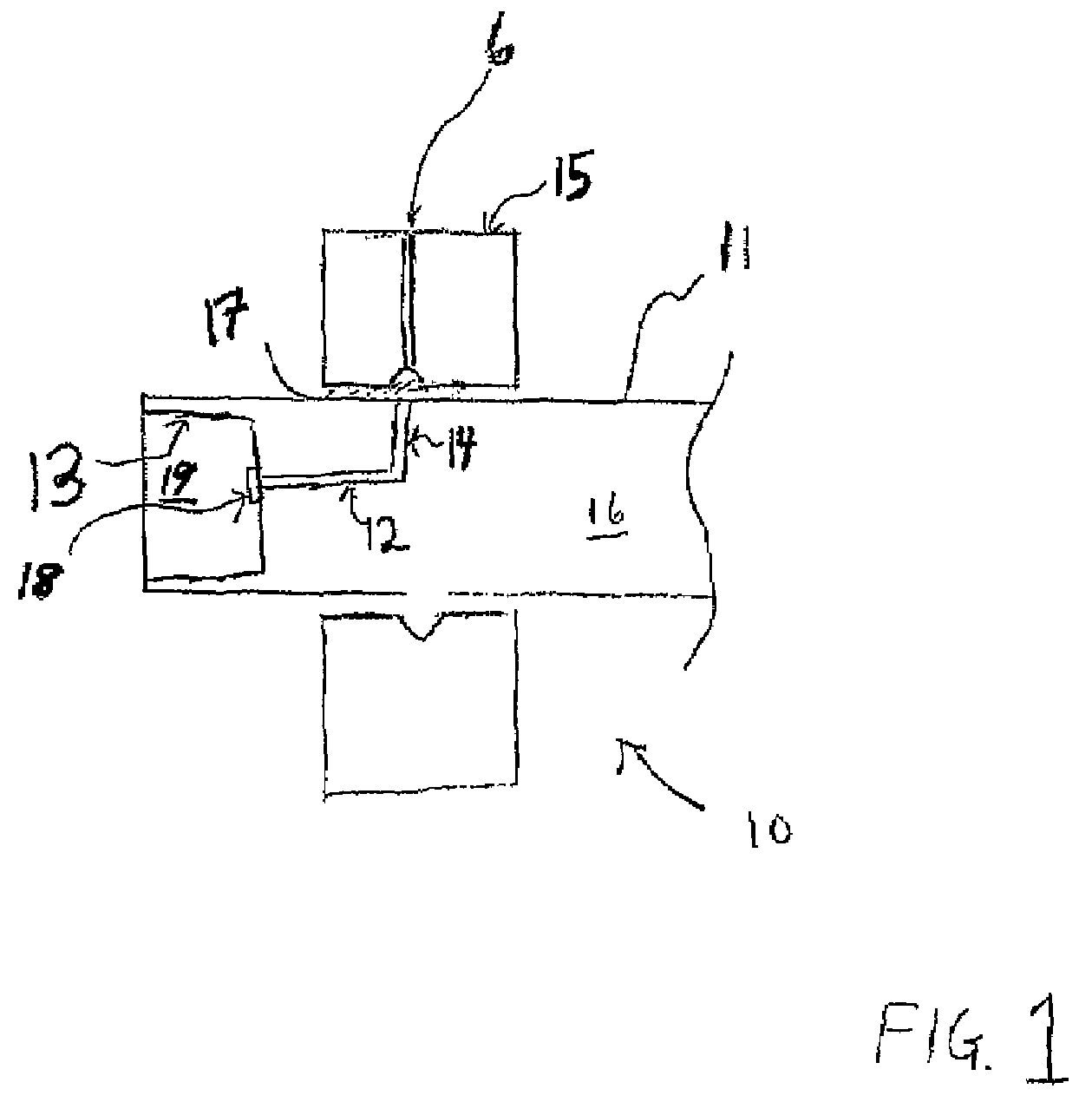
[0013]FIG. 1 illustrates a schematic illustration of one embodiment of a system 10 for lubricating a power transmitting element, such as a spline, a keyway, and the like (not shown), via an engine crankshaft 16 in accordance with at least one aspect of the present invention. A first oil passage 12 is provided in the center of an end 11 of the crankshaft 16. As shown, and in accordance with at least one embodiment of the present invention, the end 11 is the Power Take-Off (PTO) end of the crankshaft 16. It is contemplated and considered within the scope of the present invention, however, that another location on the crankshaft may be used, including by way of example, the end opposite the PTO end. The end 11 includes a cavity 19 with a surface 13 that includes a power-transmitting element(s) (not shown). The cavity 19 is capable of receiving an additional mechanism (also not shown) that is capable of contacting or engaging the power transmitting element used in conjunction with surfa...


PUM


Abstract

Disclosed herein is a lubrication system and method. The system includes a main engine bearing and a crankshaft in operational association with the bearing. The crankshaft includes an end having a cavity with a power transmitting element (e.g., splines). The cavity can receive and engage an additional mechanism to transmit power thereto. The crankshaft further includes a first oil passage that is disposed within the end and a second oil passage that extends from the main engine bearing into the crankshaft. The first oil passage intersects the second oil passage. The system also includes a pump mechanism for circulating lubricating oil from the main engine bearing to the crankshaft through the second oil passage and the first oil passage, and to the cavity to lubricate the power transmitting element. During engine operation, a constant supply of lubricating oil can be provided to the power transmitting element to reduce component wear.

Description

CROSS-REFERENCE TO RELATED APPLICATIONS[0001]--STATEMENT REGARDING FEDERALLY SPONSORED RESEARCH OR DEVELOPMENT[0002]--FIELD OF THE INVENTION[0003]The present invention relates to a lubrication system, and more particularly to a system and method for lubricating power transmitting elements. In one aspect, the invention relates to a spline lubrication system.BACKGROUND OF THE INVENTION[0004]Without proper lubrication to flush away or otherwise remove contaminants, power transmitting elements in engines progressively wear during use. Such wear results in decreased service life of a given piece of equipment. For example, a typical engine with a crankshaft employing internal splines may have a desired service life of 1500 hours. However, during engine use, the slight relative movement between the internal splines and the complementary external splines of an additional component engaged with the internal splines results in fretting and / or corrosion on the splines such that routine mainten...

Claims


Application Information

Patent Timeline
IPC IPC(8): F01M1/00
CPCF01M1/02F01M2001/062F01M11/02
Inventor JANKUSKI, GEORGE A.
Owner KOHLER CO
Why Eureka
Try Eureka