Reel unit of spinning reel

a technology of reel unit and reel body, which is applied in the field of reel unit, can solve the problems of difficult to form a reel unit with a quality appearance, foreign materials such as bait and dust are attached to the recesses, etc., and achieve the effect of easy fixing of the cover member

Active Publication Date: 2008-06-26
SHIMANO INC
View PDF8 Cites 37 Cited by
  • Summary
  • Abstract
  • Description
  • Claims
  • Application Information

AI Technical Summary

Benefits of technology

[0030]According to the present invention, the cover member is fixed to the reel body (or the lid member) by fixing the front end portion of the boss to the intermediate member being disposed non-movably with respect to the reel body (or the lid member). Therefore, it is possible to easily fix the cover member to the reel body (or the lid member), and it is also possible to prevent the screw member from being exposed to the rear portion of the reel unit.
[0031]According to the another present invention, the cover member is fixed to the reel body (or the lid member) when the retaining member retaining the first fixing means is disposed in the accommodation space so as to be non-movable with respect to the reel body (or the lid member) and the retained first fixing means is fixed to the front end portion of the boss by a tool from outside. Accordingly, when a screw member is used as the first fixing means, it is possible to use a short screw member. Therefore, it is possible to easily fix the cover member to the reel body (or the lid member), and it is also possible to prevent the screw member from being exposed to the rear portion of the reel unit.
[0032]According to the still another present invention, it is possible to fix the intermediate member to the reel body (or the cover member) while the intermediate member is provided between the cover member and the reel body and the intermediate member is preliminarily fixed to the cover member (or the reel body). Accordingly, when a screw member is used as the first fixing means, it is possible to use a short screw member. Therefore, it is possible to easily fix the cover member, and it is also possible to prevent the screw member from being exposed to the rear portion of the reel unit by mounting the first fixing means from the frontward of the reel body.

Problems solved by technology

Therefore, it is difficult to form a reel unit with a quality appearance.
In addition, there is a possibility that foreign materials such as bait and dust are attached to the recesses.

Method used


Image

  • Reel unit of spinning reel
  • Reel unit of spinning reel
  • Reel unit of spinning reel

Examples


first embodiment

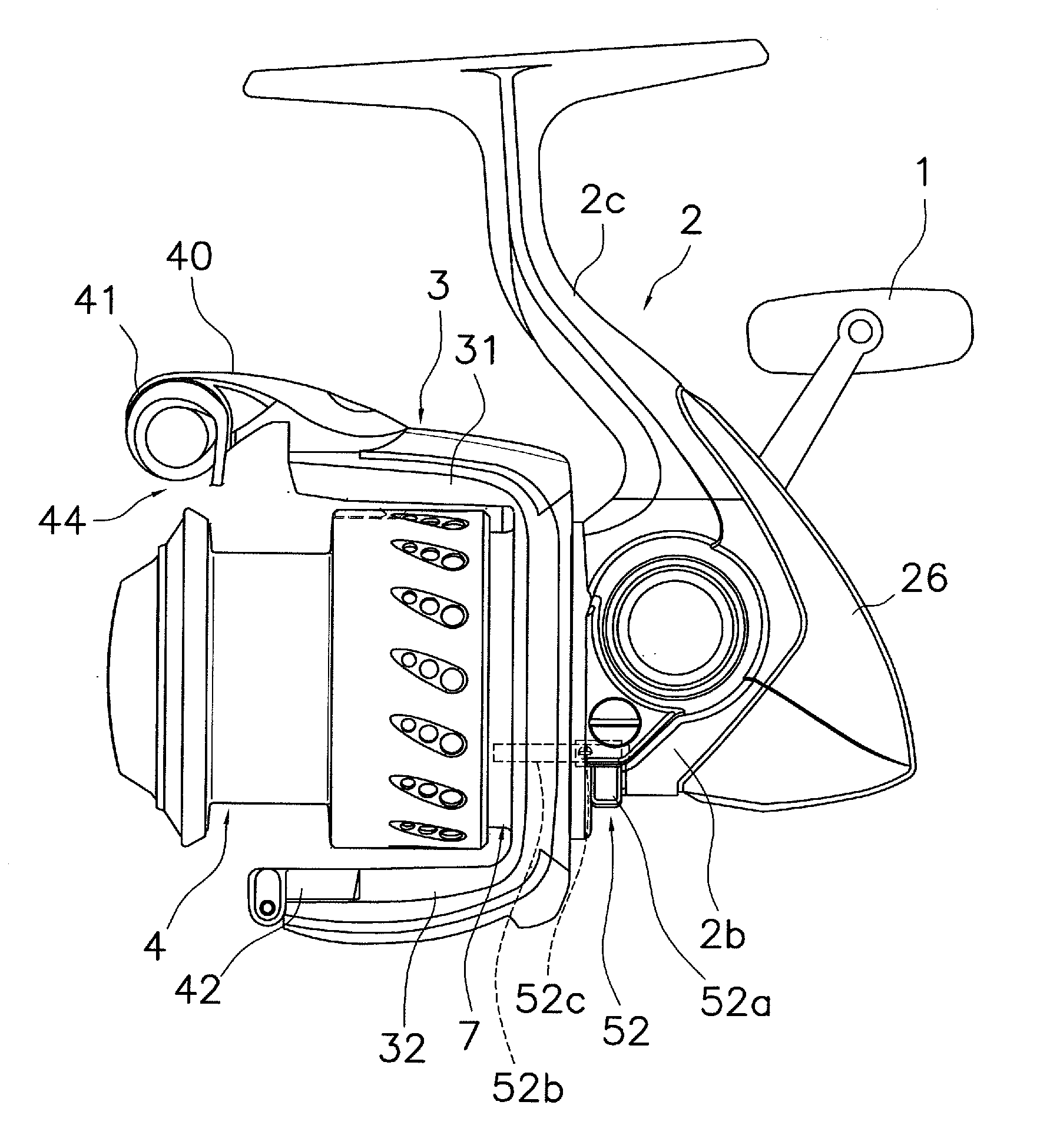
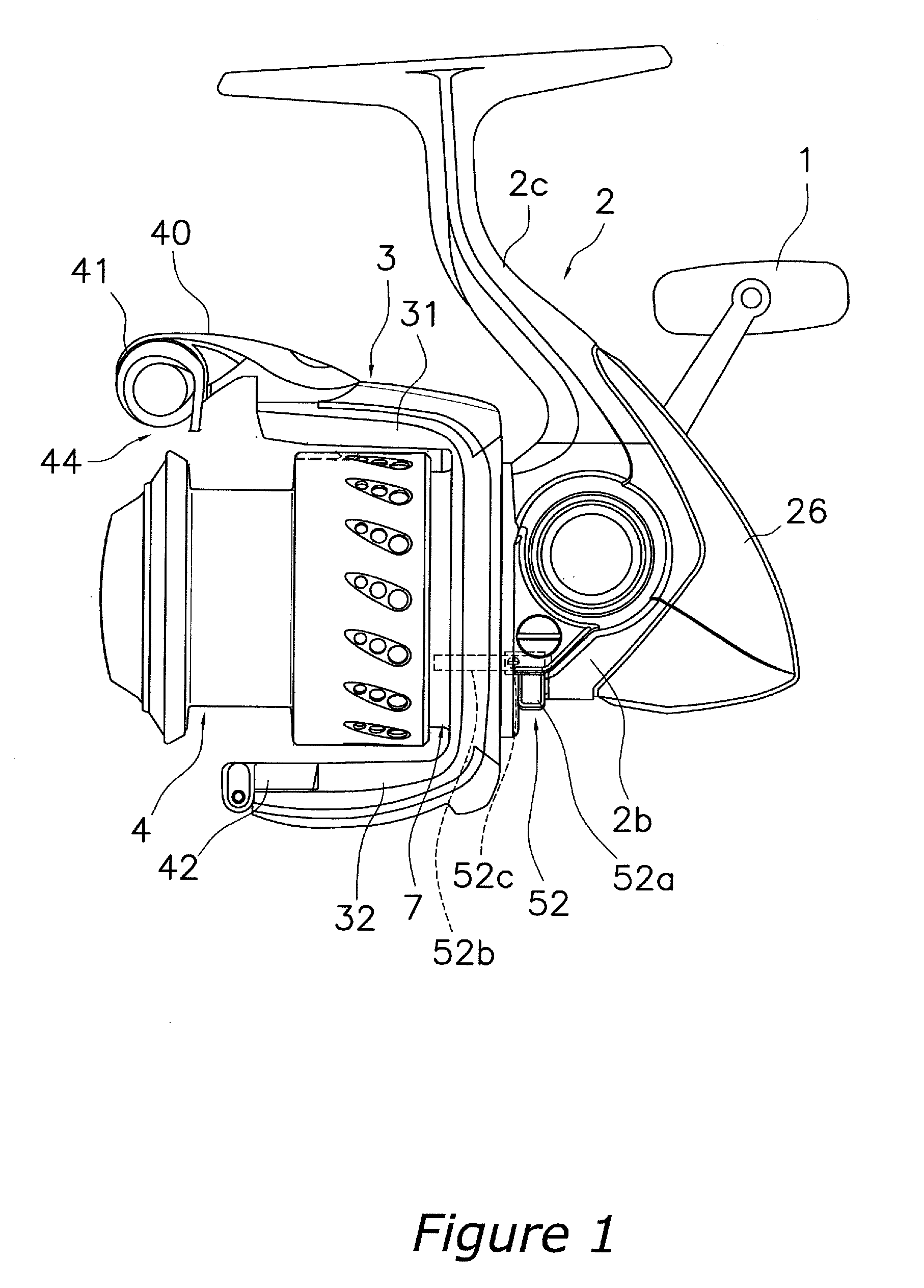
[0055]As illustrated in FIG. 1, a spinning reel in accordance with an embodiment of the present invention includes a handle 1, a reel unit 2 that rotatably supports the handle 1, a rotor 3, and a spool 4. The rotor 3 is rotatably supported on the front portion of the reel unit 2. The spool 4 serves to wind fishing line around its outer peripheral surface, and is disposed on the front portion of the rotor 3 so as to be allowed to move in a front-to-rear direction. Note that the handle 1 is capable of being mounted to either the left side or the right side of the reel unit 2.

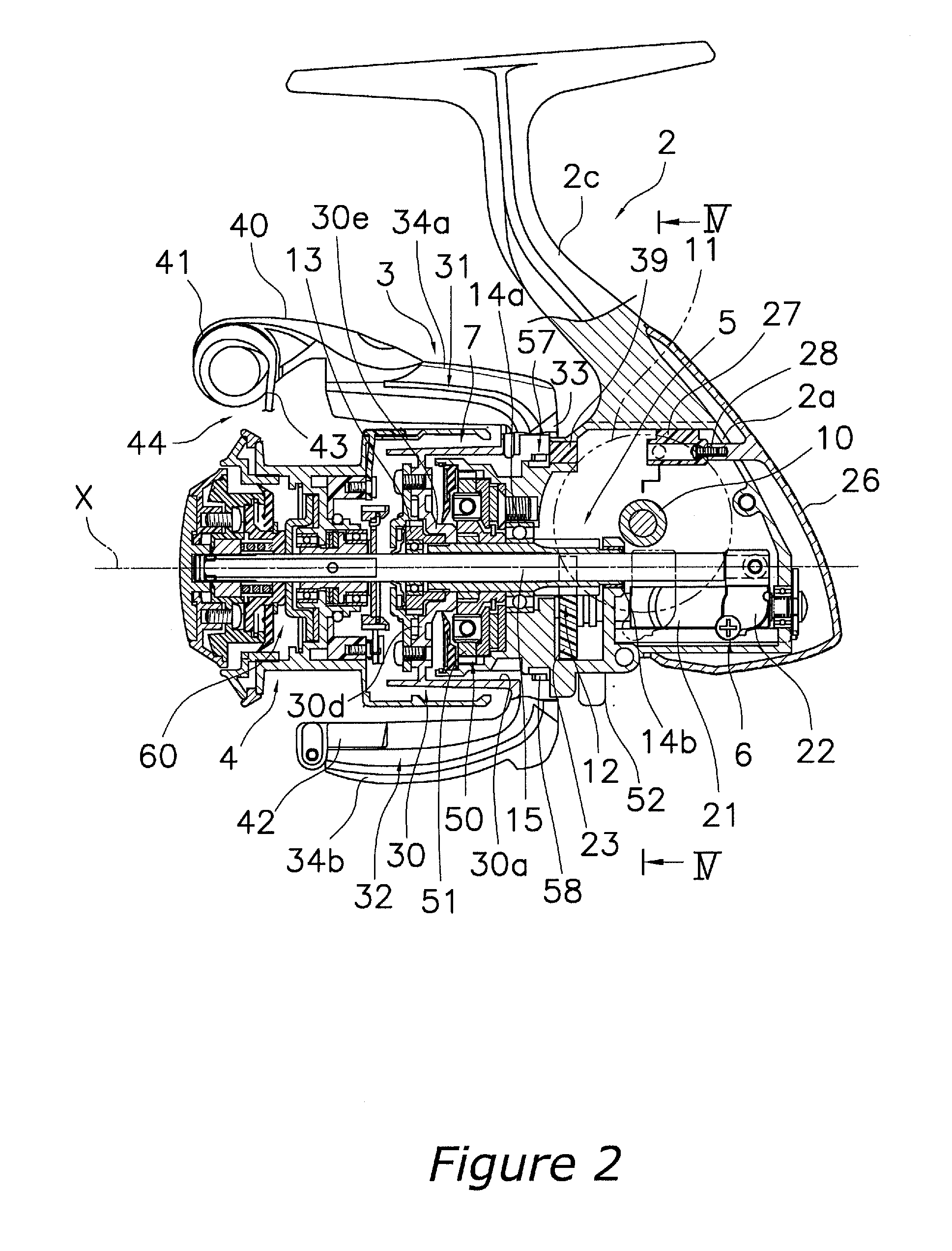
[0056]As illustrated in FIGS. 2 and 3, the reel unit 2 includes a reel body 2a having an accommodation space RA in its interior, and a lid member 2b (see FIG. 3) detachably / reattachably mounted to the reel body 2a so as to enclose the accommodation space RA formed in the interior of the reel body 2a. In addition, the reel unit 2 includes a reel unit protection member 26 (an example of the cover member) that covers...

second embodiment

[0118]As illustrated in FIG. 7, according to the second embodiment, a retaining member 127 of a reel unit 102 is integrally formed with a reel body 102a. In addition, a tapping screw, which is capable of forming a female threaded portion when screwed into a portion, is also used as a screw member 128.

[0119]As illustrated in FIG. 7, the retaining member 127 is a plate-shaped member that is integrally formed with an upper portion or a wall portion of the reel body 102a, for instance. A head portion accommodation portion 127d and a through hole 127e are formed in the retaining member 127 so as to be concentrically disposed with the first and second insertion holes 102q and 102j. A head portion 128a of a screw member 128 is allowed to be accommodated in the head portion accommodation portion 127d, and a shaft portion 128b of the screw member 128 is allowed to be retained by the through hole 127e.

[0120]A threaded hole 126d in which a female threaded portion is formed by the screw member...

third embodiment

[0128]In the first and second embodiments, the intermediate member or the retaining member 27, 127 is used for retaining the first screw member 28. In the third embodiment, the intermediate member is used for fixing the reel unit protection member to reel unit.

[0129]As illustrated in FIG. 14, the reel body 302a of the reel unit 302 is made of a light alloy such as a magnesium alloy or an aluminum alloy, and is formed integrally with a T-shaped rod attachment leg 302c that is formed on the top of the reel body 302a to extend in a front-to-rear direction as is the case with the first embodiment. The accommodation space RA of the reel body 302a accommodates a rotor driving mechanism 5 and an oscillation mechanism 6 as is the case with the first embodiment. A first flange portion 302d1 and a cylindrical portion 302e are formed on the front end of the reel body 302a. The first flange portion 302d1 is formed in a substantially semicircular shape and makes up a part of a circular flange. T...


PUM


Abstract

An object of the present invention is to make it possible to easily fix a cover member to a reel unit of a spinning reel while exposure of a fixing member to a rear portion of the reel unit is reduced. A reel unit includes a reel body, a lid member, a reel unit protection member, and an intermediate member. The reel body includes an accommodation space that opens to a lateral side, a first insertion hole that is communicated with the accommodation space, and a second insertion hole that is disposed on the opposite side of the first insertion hole and is communicated with the accommodation space. The lid member is detachably/reattachably mounted to the reel body so as to cover the accommodation space. The reel unit protection member is mounted from backward so as to cover the reel body and the lid member, and includes a boss that passes through the first insertion hole from a rear portion of the reel body and protrudes toward the accommodation space. The intermediate member is non-movably provided in the reel body within the accommodation space, and retains a screw member fixed to a front end portion of the boss in the accommodation space.

Description

CROSS-REFERENCE TO THE RELATED APPLICATIONS[0001]This application claims priority to Japanese Patent Application Nos. 2006-344913 and 2006-344914. The entire disclosure of Japanese Patent Application Nos. 2006-344913 and 2006-344914 is hereby incorporated herein by reference.TECHNICAL FIELD[0002]The present invention relates to a reel unit, and in particular to a reel unit of a spinning reel that is mounted to a fishing rod and is capable of reeling out fishing line.BACKGROUND ART[0003]A spinning reel includes a reel unit, a rotor that is rotatably supported on the front portion of the reel unit, and a spool that fishing line is wound around the outer peripheral surface thereof. The reel unit includes a reel body and a lid member. The reel body has an accommodation space in the interior thereof, and the accommodation space opens to the lateral side. The lid member is detachably / reattachably mounted to the reel body so as to cover the opening of the reel body. In the conventional ree...

Claims


Application Information

Patent Timeline
Patent Type & Authority Applications(United States)
IPC IPC(8): A01K89/01
CPCA01K89/01A01K89/027
Inventor KITAJIMA, KEIGOHIRAOKA, HIROKAZUMATSUO, SHINGO
Owner SHIMANO INC
Why Eureka
Try Eureka