

Autonomous passenger seat
a passenger seat and seat technology, applied in the direction of seats, seating arrangements, ways, etc., can solve the problem of restricting the flexibility of cabin design
- Summary
- Abstract
- Description
- Claims
- Application Information
AI Technical Summary
Benefits of technology
Problems solved by technology
Method used
Image

Examples
Embodiment Construction
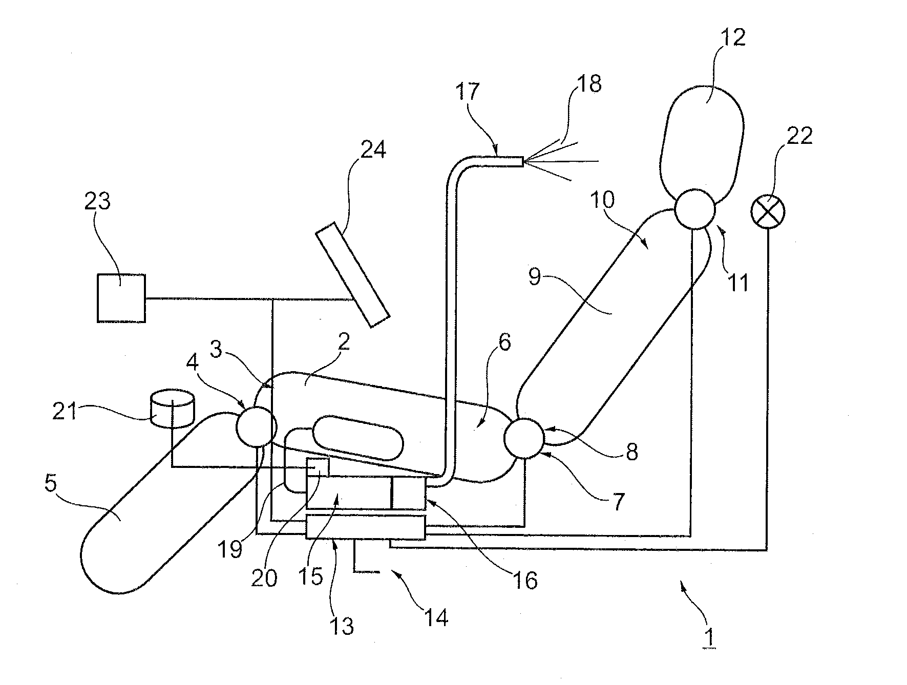
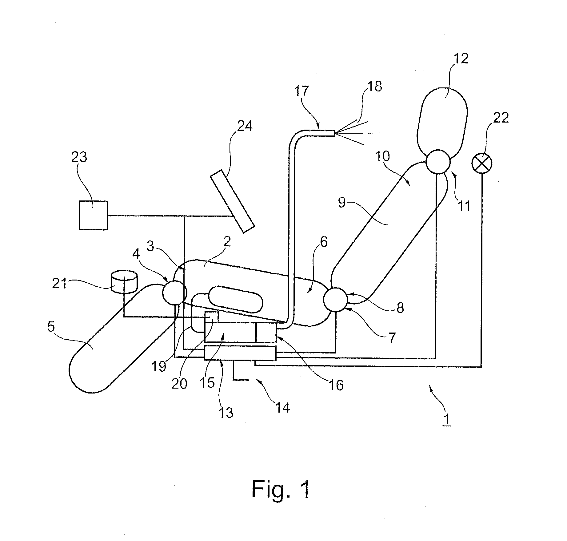
[0021]The seat device 1 of this example includes a sitting surface 2, which is connected to a leg rest 5 with its one rim area 3 via a seat control element 4. With its other rim area 6, the seat surface 2 is connected with an end 8 of a backrest 9 via an additional seat control element 7. The other end 10 of the backrest 9 is connected via an additional seat control element 11 with a headrest 12. The individual seat control elements 4, 7, 11 are controlled via a control unit 13, which is disposed below the sitting surface 2 of the seat device 1. Via a remote control unit (not shown), which may be connected to the line 14 of the control unit 13, for example, a passenger may control the control unit 13, and thereby operate the individual seat control elements 4, 7, and 11 as desired, in order to adjust the sitting surface 2, the leg rest 5, the backrest 9, or the headrest 12, according to passenger requirements.
[0022]FIG. 1 furthermore shows a fuel cell system 15, which is disposed be...
PUM
 Abstract
Description
Claims
Application Information