

Optical coding device by plasmon effect and authentication method using the device
a technology of optical coding and plasmon effect, applied in the field of optical coding devices, can solve the problems of limited number of combinations of possible combinations for forming optical codes, difficult to authenticate the nature of such luminophores, etc., and achieve the effect of difficult decoding and impossible infringing
- Summary
- Abstract
- Description
- Claims
- Application Information
AI Technical Summary
Benefits of technology
Problems solved by technology
Method used
Image

Examples
first embodiment
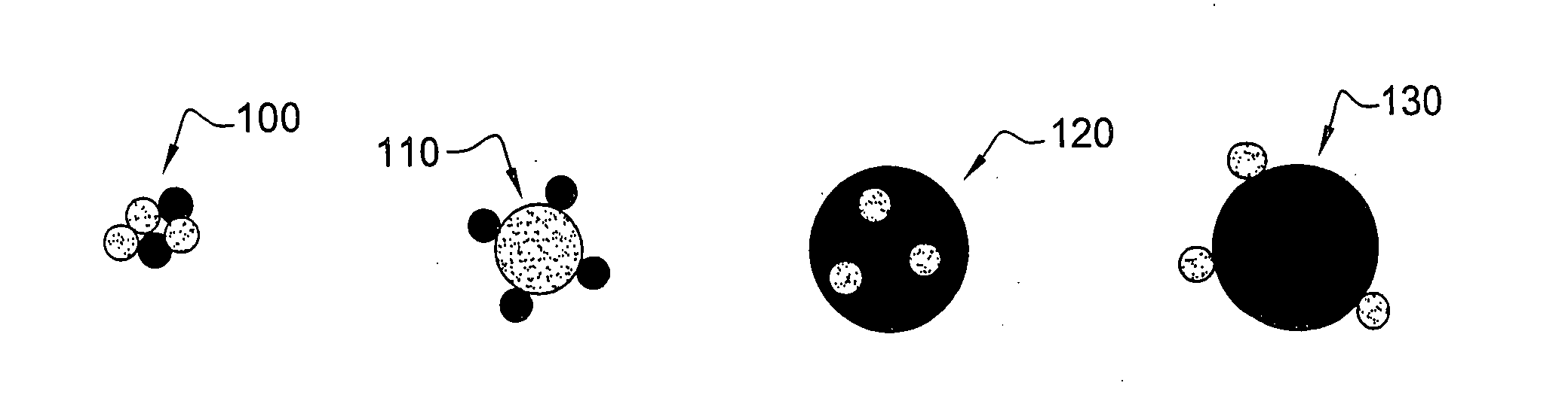
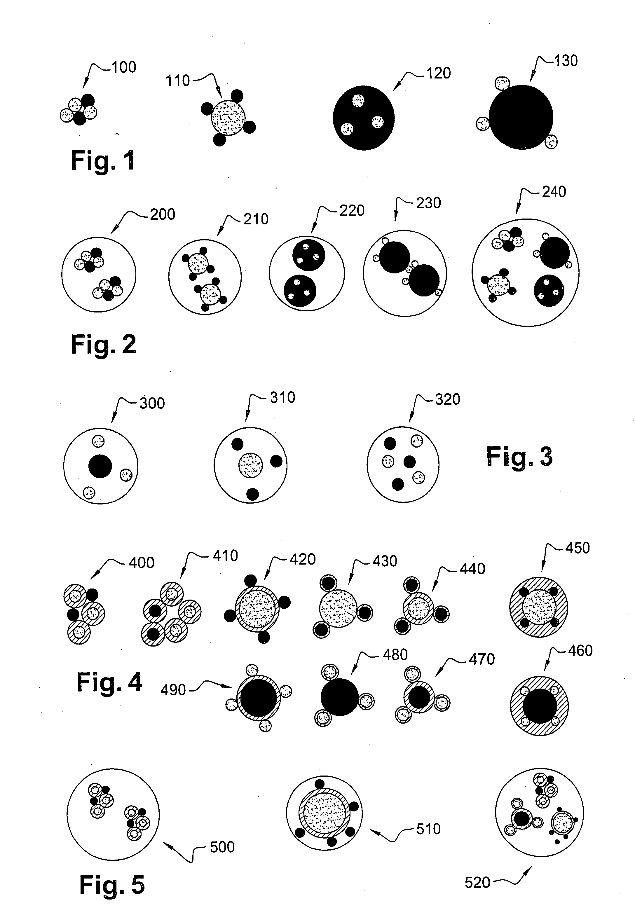
[0067]FIG. 1 shows four alternative embodiments according to the invention. The four aggregates 100, 110, 120 and 130 shown here all consist of luminophores aggregated with surface plasmon effect particles.
[0068]As may be observed, the dimensions and respective positions of the luminophores and the particles may vary from one embodiment to another. Thus, the aggregate 100 comprises two joined luminophores, for example joined by van der waals forces, having three surface plasmon effect particles. In the case of the aggregate 100, the luminophores and the particles have similar dimensions.
[0069]Conversely, the aggregate 110 comprises a large surface plasmon effect particle on which four luminophores are aggregated (at least in the plane of the sheet constituting the cross section plane of this aggregate).
[0070]The aggregate 130 corresponds to the reverse situation of the aggregate 110, where three small particles are associated with one “large” luminophore.
[0071]The aggregate 120 is a...
second embodiment
[0073]FIG. 2 shows five alternative embodiments according to the invention. The five aggregates 200, 210, 220, 230 and 240 all comprise luminophores combined with surface plasmon effect particles. The whole, being encapsulated or embedded within an envelope made from a material transparent to infrared, visible or ultraviolet rays. As may be observed in FIG. 2, the clusters encapsulated by the envelopes are identical to the aggregates 100, 110, 120 and 130 shown in FIG. 1. Thus, the aggregate 200 comprises two identical combinations to the aggregate 100, embedded in an envelope. Similarly, the aggregate 210 comprises two identical combinations to the aggregate 110, embedded in an envelope, and so on.
[0074]The aggregate 240 comprises an envelope encapsulating four combinations identical respectively to the aggregates 100, 110, 120 and 130.
[0075]In consequence, just as each aggregate 100, 110, 120 and 130 in FIG. 1 is capable of constituting an optical coding device having a unique, he...
third embodiment
[0076]FIG. 3 corresponds to the invention, in which the aggregates, 300, 310 and 320 all consist of one or more luminophores, one or more surface plasmon effect particles, the whole being encapsulated by an envelope similar to the one making up the aggregates 200, 210, 220, 230 and 240 in FIG. 2.
[0077]However, in the case of FIG. 3, the luminophores and the particles are isolated within each envelope.
[0078]According to the invention, the distance between a luminophore and a particle is shorter than a few tens of nanometres, preferably to 30 nm. As already stated above, this distance enables the particles and the luminophores to interact in order to modulate the luminous spectrum re-emitted by luminescence. To control this distance or interval between luminophores and particles, it is desirable to control the relative proportions of luminophores, particles and material making up this envelope during their blending.
[0079]As in the case in FIG. 1, the component elements of the aggregat...
PUM
| Property | Measurement | Unit |
|---|---|---|
| distance | aaaaa | aaaaa |
| wavelength | aaaaa | aaaaa |
| wavelength | aaaaa | aaaaa |
Abstract
Description
Claims
Application Information