
Chopper regulator circuit

a regulator circuit and regulator technology, applied in the direction of circuit arrangement, static indicating device, instruments, etc., can solve the problems of difficult to make each one of them emit light properly, large variation of drive voltage of organic el elements, and high power loss of resistors b>7/, so as to reduce damage and other adverse effects.

Inactive Publication Date: 2008-06-26
SHARP KK
View PDF3 Cites 36 Cited by
  • Summary
  • Abstract
  • Description
  • Claims
  • Application Information

AI Technical Summary

Benefits of technology

[0016]In view of the conventionally encountered inconveniences mentioned above, it is an object of the present invention to provide a chopper regulator circuit that can easily supply two loads with adequate electric power with minimum disadvantages such as an increase in the total number of components needed.

Problems solved by technology

Inconveniently, however, the higher the voltage VREF, the higher the power loss in the resistor 7.
If, therefore, the two loads differ in the amount of electric power they need for proper light emission, it may be difficult to make each one of them emit light properly.
Or, the organic EL element may suffer from large variations in its drive voltage.
Inconveniently, however, providing components—such as a power source and a drive circuit, dedicated to each load leads to an increase in the total number of components needed, hampering the miniaturization and cost reduction of devices incorporating the chopper regulator.

Method used


Image

  • Chopper regulator circuit
  • Chopper regulator circuit
  • Chopper regulator circuit

Examples


first embodiment

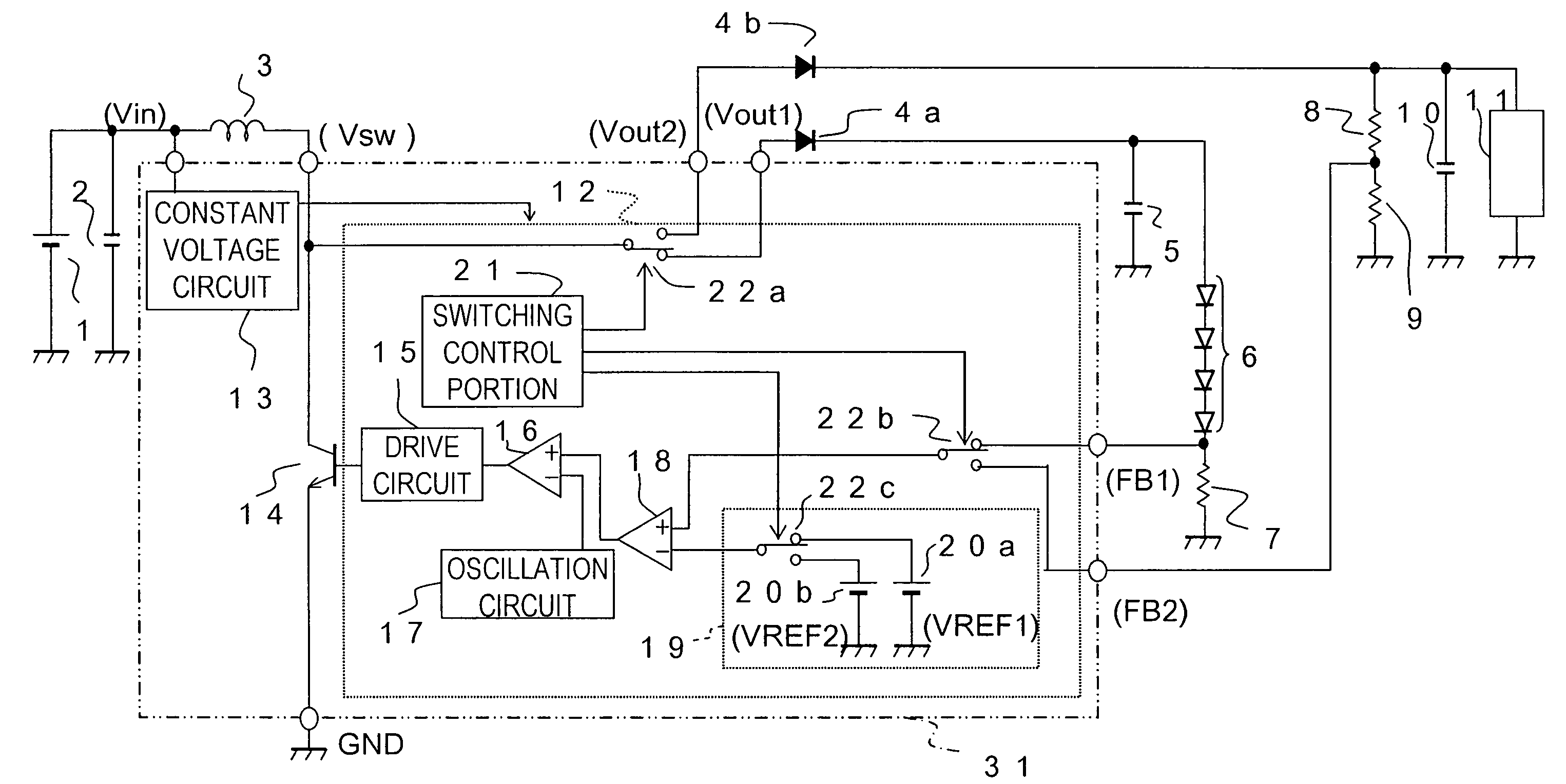
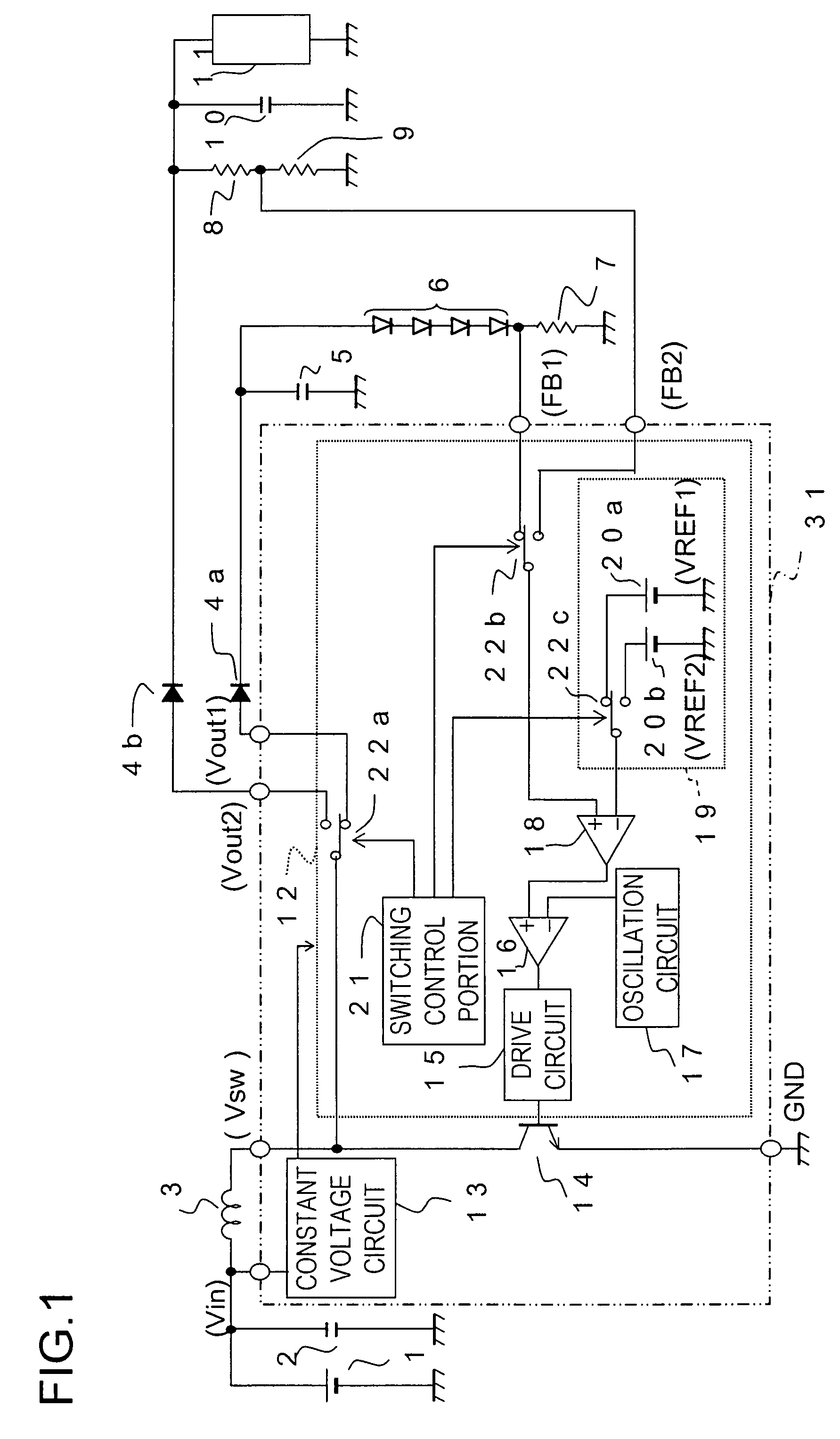
[0056]Embodiment 1: As the present invention, a chopper-regulator-type power supply circuit will be described below that is connected to an LED group (which may be a single LED, or a plurality of LEDs connected in series) and an organic EL element to supply electric power selectively to one of them. The configuration of this power supply circuit is shown in FIG. 1.

[0057]As shown in FIG. 1, the power supply circuit includes a DC (direct-current) power source 1, an input capacitor 2, a coil 3, a first diode 4a, a second diode 4b, a first output capacitor 5, resistors 7 to 9, a second output capacitor 10, a chopper regulator IC 31, and other components. Configured as shown in FIG. 1, the power supply circuit supplies the LED group 6 and the organic EL element 11 with electric power.

[0058]The negative terminal of the DC power source 1 is grounded, and the positive terminal of the DC power source 1 is connected to one end of the input capacitor 2 and to one end of the coil 3. The other e...

embodiment 1

[0075]As described above, the power supply circuit of Embodiment 1 is a chopper-regulator-type power supply circuit that is connected to an LED group 6 and an organic EL element 11 to supply them with electric power. The power supply circuit includes components (such as a DC power source 1 and a coil 3) for outputting electric power to those loads, components (such as a resistor 7) for detecting as a detected voltage the current outputted to the LED group 6, and components (such as resistors 8 and 9) for detecting as a detected voltage the voltage outputted to the organic EL element 11.

[0076]The power supply circuit further includes a first and a second reference voltage source 20a and 20b for generating reference voltages VREF1 and VREF2 respectively and components (such as a drive circuit 15, a PWM comparator 16, and an error amplifier 18) for comparing two input voltages to control, based on the result of the comparison, the amount of outputted electric power.

[0077]The power supp...

embodiment 2

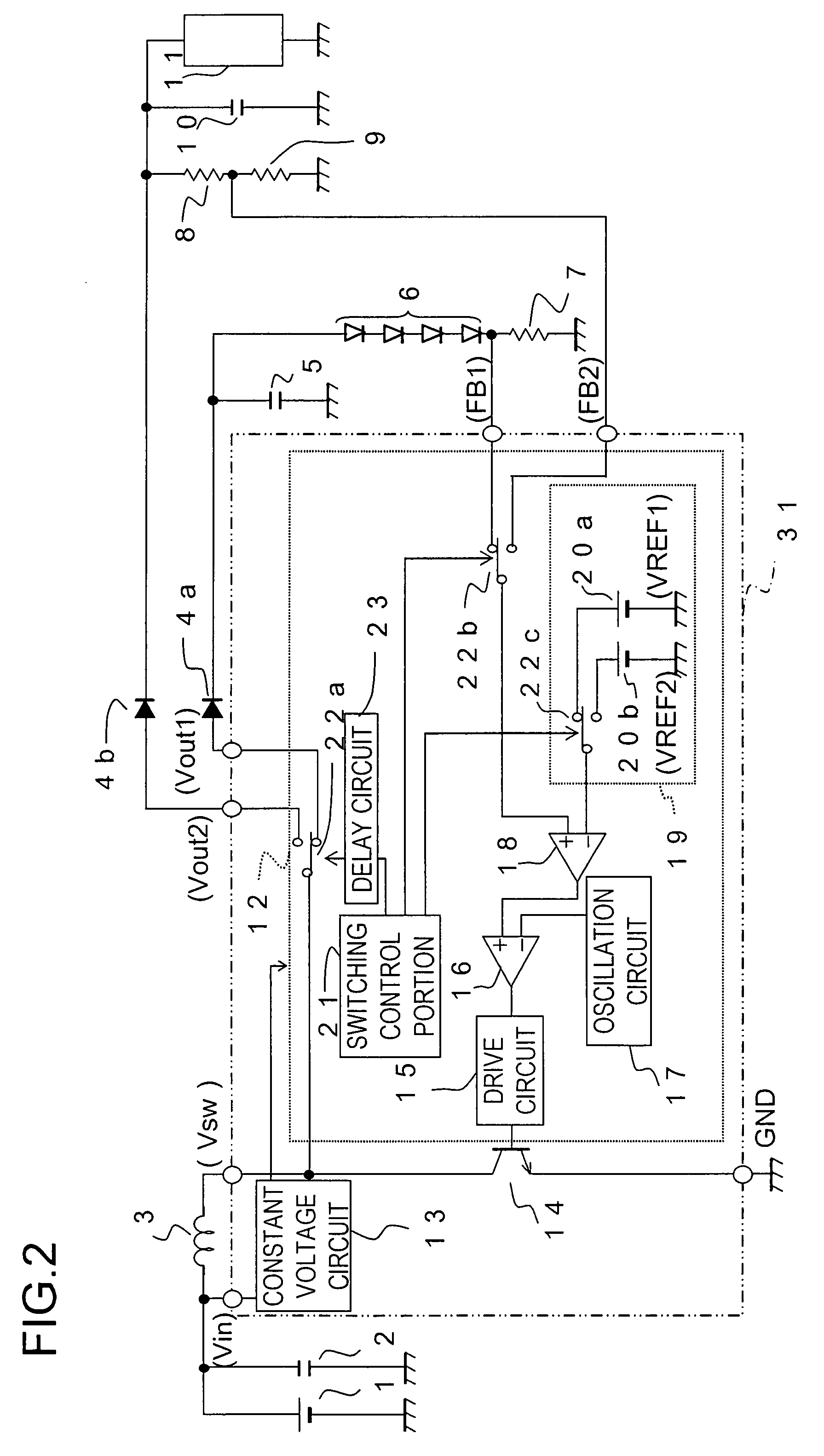
[0081]This makes it possible, without complicating the control performed by the switching control portion 21, to perform the switching (input switching) between sources from which to obtain the voltage to be fed back and between reference voltage sources 20a and 20b properly prior to the switching (load switching) between destinations to which to supply electric power. Thus, even when electric power starts to be supplied before the feedback voltage sources and the reference voltage sources 20a and 20b are properly set (ready to operate), with Embodiment 2, it is possible to prevent instability in the control of the supply of electric power as much as possible.

[0082]Embodiment 3: Next, as a third embodiment of the present invention, again, a power supply circuit will be described below. The configuration here is largely the same as that in Embodiment 1, the chief difference lying in the configuration of the reference voltage circuit 19. Accordingly, no overlapping description will be...


PUM


Abstract

A chopper regulator circuit has: a power output portion for a first and a second load; a first output detection portion detecting the output to the first load; a second output detection portion detecting the output to the second load; a first and a second reference voltage generation portion; an output control portion controlling the amount of outputted electric power based on a result of comparison between two input voltages; and a switching control portion switching which of the first and second loads to supply electric power to and switching what voltages to handle as the input voltages. The input voltages are so switched that, when electric power is supplied to the first load, the detected voltage detected by the first output detection portion and the reference voltage generated by the first reference voltage generation portion are handled as the input voltages and, when electric power is supplied to the second load, the detected voltage detected by the second output detection portion and the reference voltage generated by the second reference voltage generation portion are handled as the input voltages. Thus, a chopper regulator circuit is realized that can easily supply two loads with adequate electric power with minimum disadvantages such as an increase in the total number of components needed.

Description

[0001]This nonprovisional application claims priority under 35 U.S.C. § 119(a) on Patent Application No. 2006-344564 filed in Japan on Dec. 21, 2006, the entire contents of which are hereby incorporated by reference.BACKGROUND OF THE INVENTION[0002]1. Field of the Invention[0003]The present invention relates to a chopper regulator circuit that supplies electric power to a plurality of electrical loads.[0004]2. Description of Related Art[0005]Backlights for a liquid crystal display portion in mobile phones, mobile terminals, and the like generally use white LEDs (light-emitting diodes). These white LEDs are typically driven by step-up chopper regulators. On the other hand, nowadays, organic EL (electroluminescence) elements are increasingly used in such a display portion, contributing to the slimming-down of the display portion.[0006]White LEDs mentioned above require a forward voltage as high as about 4 V, and their forward voltage tends to vary from one LED to another. For improved...

Claims


Application Information

Patent Timeline
IPC IPC(8): G09G3/10H02J3/14
CPCH02M3/156H05B35/00H02M2001/009H02M1/009
Inventor SUZUKI, TOMOHIRO
Owner SHARP KK
Learn More