Radar controlled automatic target illumination system

a technology of automatic target illumination and radar control, which is applied in the direction of way illumination vessel signalling, instruments, measurement devices, etc., can solve the problems of limited effectiveness of manual operation of such light beams in illuminating such targets, and achieve the effect of reducing back glar

Inactive Publication Date: 2008-06-26
GLEN E ROBERTSON
View PDF12 Cites 13 Cited by
  • Summary
  • Abstract
  • Description
  • Claims
  • Application Information

AI Technical Summary

Benefits of technology

[0015]It is therefore an object of this invention to provide a radar controlled automatic target illumination system for marine vessels which will automatically identify a target of interest or concern and illuminate that target by activating an appropriately-aimed light within an array of lights to assist the operator of the vessel during nighttime operations.

Problems solved by technology

Although watercraft are typically provided with a rotatable light beam mechanism for spotting such targets in the dark to aid in navigation and to avoid collision therewith, an operator manually directing the rotational position of such light beams is very limited in their effectiveness of illuminating such targets simply because the operator does not have an initial indication of the general direction in which to point the light beam.

Method used


Image

  • Radar controlled automatic target illumination system
  • Radar controlled automatic target illumination system
  • Radar controlled automatic target illumination system

Examples


Embodiment Construction

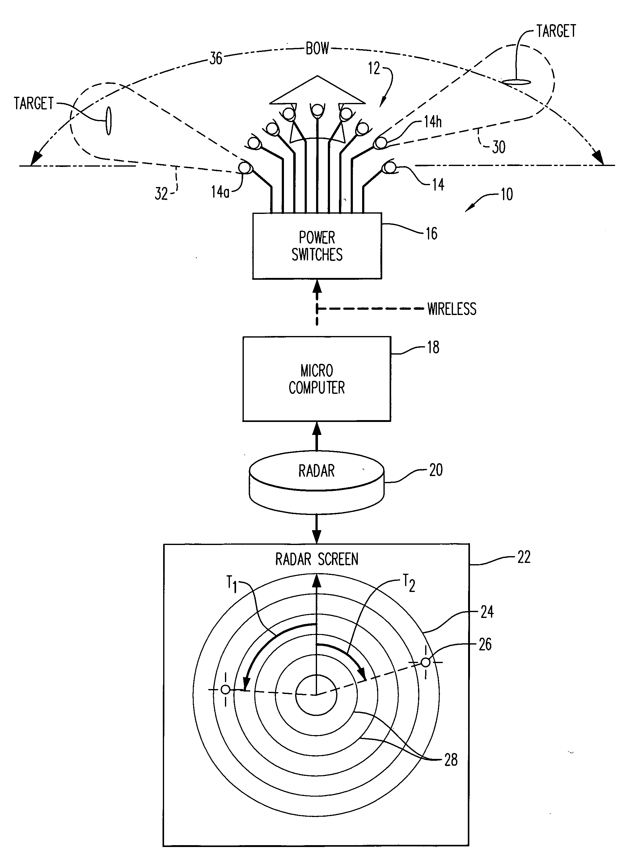
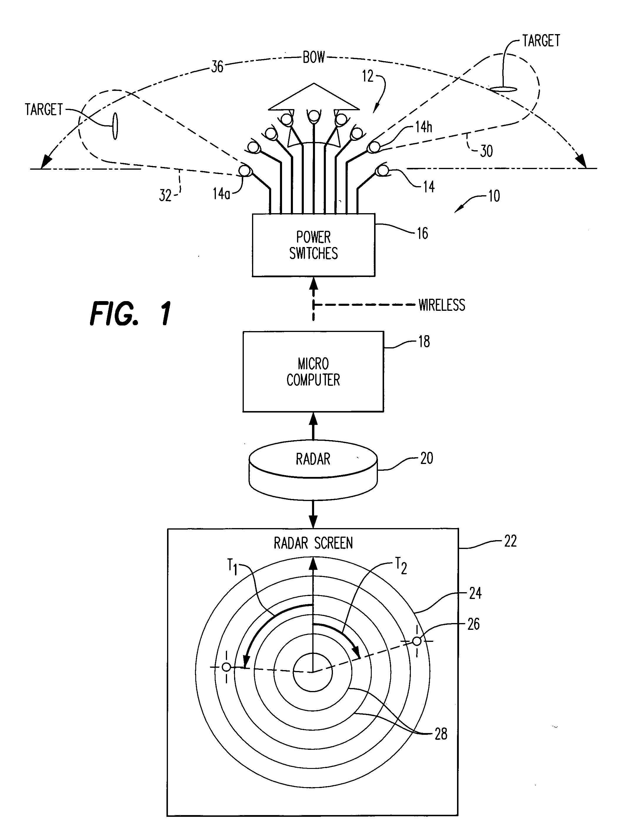
[0026]Referring now to the drawings, and firstly to FIGS. 1 and 2, the preferred embodiment of the invention utilized in conjunction with marine vessels or watercraft is there shown generally at numeral 10. This radar-controlled automatic target illumination system 10 includes a radar transmitter / signal receiver 20 typically mounted at an elevated point on the structure of a marine vessel. The radar unit 20 transmits radial signals and receives reflected signals back identifying above-water targets in a conventional manner and displays those reflected target signals on a visual display 22 viewable by the operator of the marine vessel. The screen 24 will display each of the targets shown typically at 26 and will also typically include distance estimates in the form of distance positioning within concentric rings 28 marked on the viewing screen 24. A relative bearing or azimuth angle T1, T2, T3 . . . may also be shown or measurable from the screen 24.

[0027]A most important aspect of t...


PUM


Abstract

A radar controlled automatic target illumination system for marine and other moving vessels. A radar system operably connected to the vessel produces an electronic signal corresponding to an azimuth of a target relative to, and in proximity to the vessel. An array of lights are connected to the vessel, each light being aimed outwardly in a different lighting sector, the sectors being adjacent one to another around the vessel, each of said lights, when automatically activated, illuminating one lighting sector. An electronic processor is operably connected between the radar system and the array of lights for the automatic selective activation of one or more of the lights to illuminate the target within a corresponding lighting sector which the radar system has identified.

Description

CROSS-REFERENCE TO RELATED APPLICATIONS[0001]Not applicableSTATEMENT REGARDING FEDERALLY SPONSORED RESEARCH OR DEVELOPMENT[0002]Not applicableINCORPORATION-BY-REFERENCE OF MATERIAL SUBMITTED ON A COMPACT DISC[0003]Not applicableBACKGROUND OF THE INVENTION[0004]1. Field of the Invention[0005]This invention relates generally to vehicle directional safety lighting systems and devices for illuminating nearby targets with a searchlight or spotlight to assist the helmsman in guiding his vessel safely.[0006]2. Description of Related Art[0007]Technology growth has brought many new capabilities to improve boating safety. The cost of these new capabilities has continued to drop and is now allowing the small boat owner to have high technology products that previously were only available to military and commercial ships or Yachts of wealthy owners. A prime example has been marine radar, first used by the military then by large commercial ships; next by larger fishing boats and yachts and now by...

Claims


Application Information

Patent Timeline
Patent Type & Authority Applications(United States)
IPC IPC(8): G01S13/04
CPCB63B45/02G01S13/04B64D47/06
Inventor ROBERTSON, GLEN E.WEBSTER, JOHN
Owner GLEN E ROBERTSON
Why Eureka
Try Eureka