Supercharge Your Innovation With Domain-Expert AI Agents!

Prosthesis Component Holder Attachable to an Inserter Handle

a technology for inserters and components, applied in the field of prosthesis inserters, can solve problems such as the dislocation of the cup, the movement of the cup from the set position, etc., and achieve the effect of quick removal

Active Publication Date: 2008-06-26
VIANT AS&O HLDG LLC
View PDF4 Cites 15 Cited by
  • Summary
  • Abstract
  • Description
  • Claims
  • Application Information

AI Technical Summary

Benefits of technology

[0007]The present adaptor / holder is designed to attach to the mount (or tool) end of an inserter handle via an existing threaded interface mechanism of the handle. The adaptor / holder then utilizes the inserter handle's existing mount tensioning mechanism to accomplish the quick engagement and disengagement of a component of an orthopedic prosthesis assembly. Upon activation of the inserter handle's tensioning mechanism, the adaptor mount receives and fixes a prosthetic component to the tool end of the inserter handle for use. Deactivation of the inserter handle's tensioning mechanism is quickly accomplished with minimal manipulation to rapidly release the prosthetic component. In the cases illustrated herein, the prosthetic component to be installed is a cup insert.
[0008]An important feature of the present prosthetic component holder is that it enables the prosthetic component to be detached from the inserter handle, in situ, without having to operate the drive assembly of the handle to release the component after its installation in a patient. This feature of the present holder and handle combination eliminates the need for a threaded interface on the prosthetic component. A benefit of this feature is that, unlike prior inserter devices, the entire instrument (the handle with the holder still attached) can be quickly removed from the surgical site without having to maintain the positioning of the handle relative to the prosthetic component (e.g., an insert cup) inside the patient, while unscrewing the drive linkage assembly to separate the handle from the insert cup. Additionally, in prior inserter handles, where the inserted cup is screwed to the tool end of the drive linkage, the unscrewing of the drive linkage assembly can apply rotational torque to the installed prosthesis cup, which can potentially cause the cup to move from its set position or even to become dislodged.

Problems solved by technology

Additionally, in prior inserter handles, where the inserted cup is screwed to the tool end of the drive linkage, the unscrewing of the drive linkage assembly can apply rotational torque to the installed prosthesis cup, which can potentially cause the cup to move from its set position or even to become dislodged.

Method used


Image

  • Prosthesis Component Holder Attachable to an Inserter Handle
  • Prosthesis Component Holder Attachable to an Inserter Handle
  • Prosthesis Component Holder Attachable to an Inserter Handle

Examples


Embodiment Construction

[0017]Referring now to the drawings, the details of preferred embodiments of the present invention are graphically and schematically illustrated. Like elements in the drawings are represented by like numbers, and any similar elements are represented by like numbers with a different lower case letter suffix.

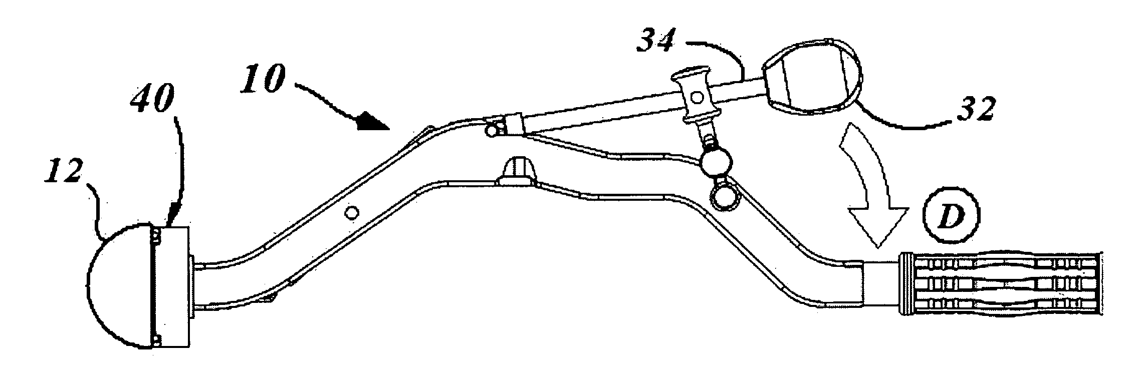
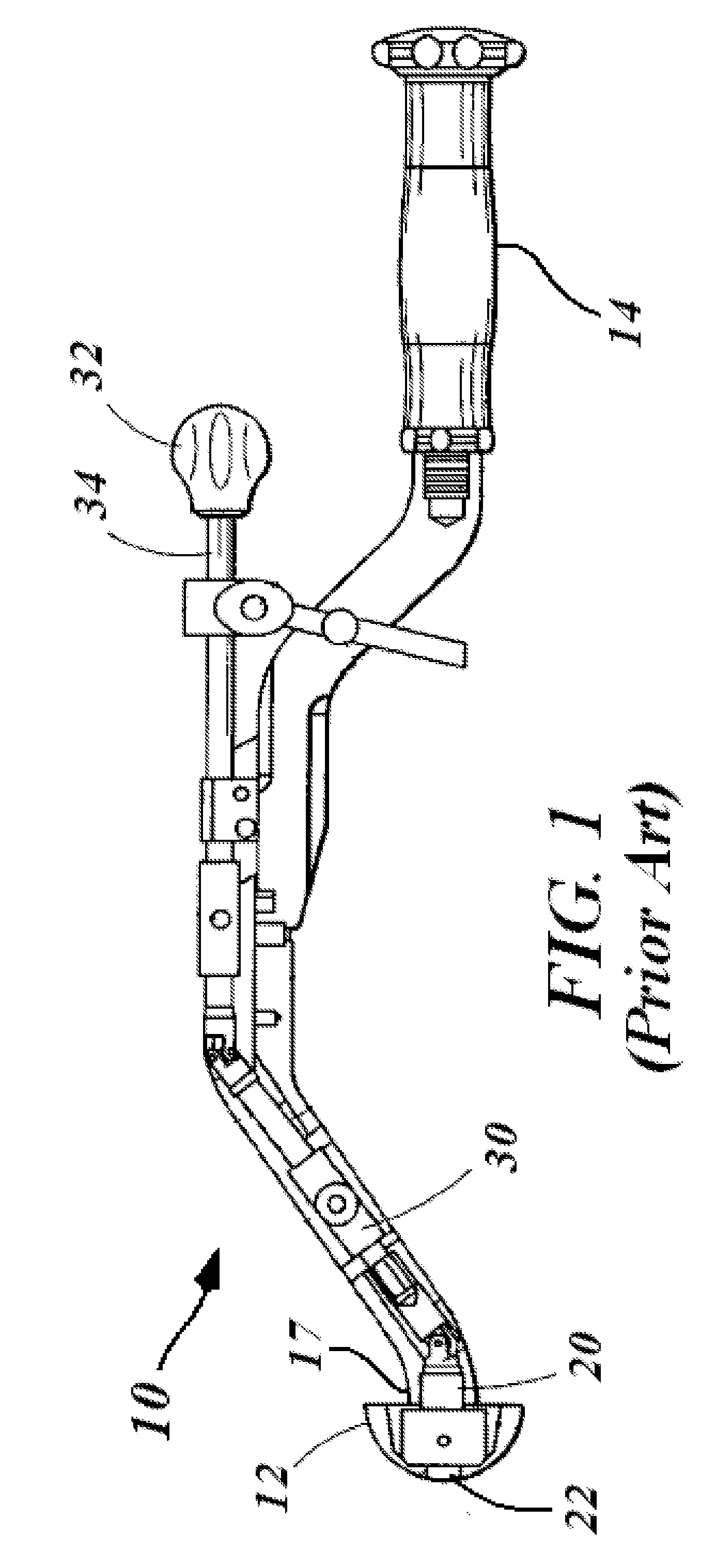
[0018]As shown in FIG. 2, the present invention is a prosthesis component holder 40 attachable to the mount / tool end 17 of an existing inserter handle 10 (see FIG. 1). The inserter handle 10 has a draw piston 20 projecting through the drive end boss 18 at its mount end 17. The draw piston 20 is operated by the lever action of tile drive chain shaft 34 of the handle 10. The holder 40 comprises an annular housing 42 attachable to the drive end boss 18 of the inserter handle 10. The housing 42 has several surfaces including: a front surface 44, a back surface 46, an outer surface 48 and an inner surface 50. The inner housing surface 50 defines an annular opening 54 in the housing 42....


PUM


Abstract

An adaptor / holder (40) is described which attaches to the front (18) of an existing orthopedic inserter / impactor handle (10) via the handle's existing threaded interface mechanism (22). The adaptor / holder (40) has an annular housing (42) that snaps onto the front (18) of the existing inserter (10), and has an internal yoke and pin assembly (70) that attached to the handle's interface mechanism (22). The holder (40) adapts the inserter (10) to much more easily and quickly release from a prosthetic component (12) after the component (12) is surgically implanted in a patient, and with less mechanical manipulation than could otherwise be accomplished using the inserter (10) alone. The adaptor / holder utilizes the inserter's existing mount tensioning (draw piston) mechanism (30) to quickly engage and disengage the prosthetic component (12). Upon activation of the inserter's tensioning mechanism (30), the holder (10) receives and fixes a prosthetic component (12) to the end (18) of the inserter (10). Deactivation of the inserter handle's tensioning mechanism (30) quickly accomplishes release of the prosthetic component (12) with minimal manipulation.

Description

[0001]The present application claims the benefit of prior filed U.S. Provisional Patent Application Ser. No. 60 / 871,300 filed 24 Dec. 2006, the content of which is incorporated herein by reference.FIELD OF THE INVENTION[0002]The present invention is in the field of orthopedic surgical instrumentation (class 606 / 53). Specifically, the present invention relates to surgical instrumentation for use in bone reparation for the manipulation, placement or removal of an internal bone prosthesis (class 606 / 53; 86). More specifically, the present invention relates to prosthesis inserters, such as impactors, adapted to place or remove a bone repairing means through forceful contact, in which momentum is transferred from the force transferring means to the reparation means (class 606 / 53; 86; 99).BACKGROUND OF THE INVENTION[0003]Surgical procedures for the implantation of orthopedic prosthetic assemblies often requires specialized tools specifically adapted for insertion of a particular component...

Claims


Application Information

Patent Timeline
Patent Type & Authority Applications(United States)
IPC IPC(8): A61B17/58A61B17/56
CPCA61F2/4609A61F2002/30471A61F2220/0091A61F2002/30635A61F2220/0025A61F2002/30507A61F2/4603
Inventor BURGI, JONAS
Owner VIANT AS&O HLDG LLC
Features
  • R&D
  • Intellectual Property
  • Life Sciences
  • Materials
  • Tech Scout
  • Unparalleled Data Quality
  • Higher Quality Content
  • 60% Fewer Hallucinations
Learn More