Drill bit with cutter element having crossing chisel crests

a cutter element and drill bit technology, applied in drill bits, earth drilling and mining, cutting machines, etc., can solve the problems of requiring considerable time, effort and expense, and the cutter element is not able to remove formation material as quickly, and the cutter element has certain limitations

Active Publication Date: 2008-07-03
SMITH INT INC
View PDF99 Cites 34 Cited by
  • Summary
  • Abstract
  • Description
  • Claims
  • Application Information

AI Technical Summary

Benefits of technology

[0018]In accordance with still other embodiments, a drill bit for cutting a borehole having a borehole sidewall, corner and bottom, comprises a bit body including a bit axis. In addition, the drill bit comprises a rolling cone cutter mounted on the bit body and adapted for rotation about a cone axis. Further, the drill bit comprises at least one cutter element having a base portion with a diameter secured in the rolling cone cutter and a cutting portion extending therefrom. The cutting portion comprising a first pair of flanking surfaces that taper towards one another to form a first elongate chisel crest, and a second pair of flanking surfaces that taper towards one another to form a second elongate chisel crest that intersects the first elongate chisel crest in top view. Moreover, the first elongate chisel crest defines a first crest tangent angle in front profile view. The first crest tangent angle at 10% of the diameter measured radially from the central axis on the first elongate chisel crest in profile view is greater than 75° and less than or equal to 90°.

Problems solved by technology

As is thus obvious, this process, known as a “trip” of the drill string, requires considerable time, effort and expense.
However, because of the conical insert's relatively narrow profile, in softer formations, it is not able to remove formation material as quickly as would an insert having a wider cutting profile.
Despite this advantage of chisel-shaped inserts, however, such cutter elements have certain limitations depending on their orientation in the rolling cone cutter.
The narrow profile may enhance the depth of formation penetration but, like a conical insert, it typically is not able to remove formation material as quickly as a wider cutting profile.
The relatively wide cutting profile tends to increase the width of the path swept by the insert, however, the wide, blunt profile of the crest may reduce formation penetration.

Method used


Image

  • Drill bit with cutter element having crossing chisel crests
  • Drill bit with cutter element having crossing chisel crests
  • Drill bit with cutter element having crossing chisel crests

Examples


Embodiment Construction

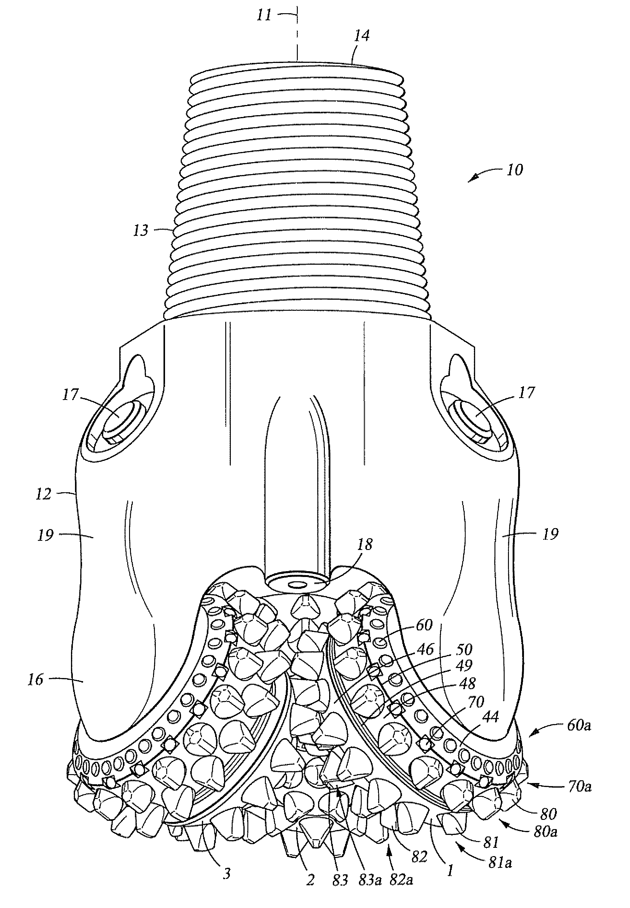
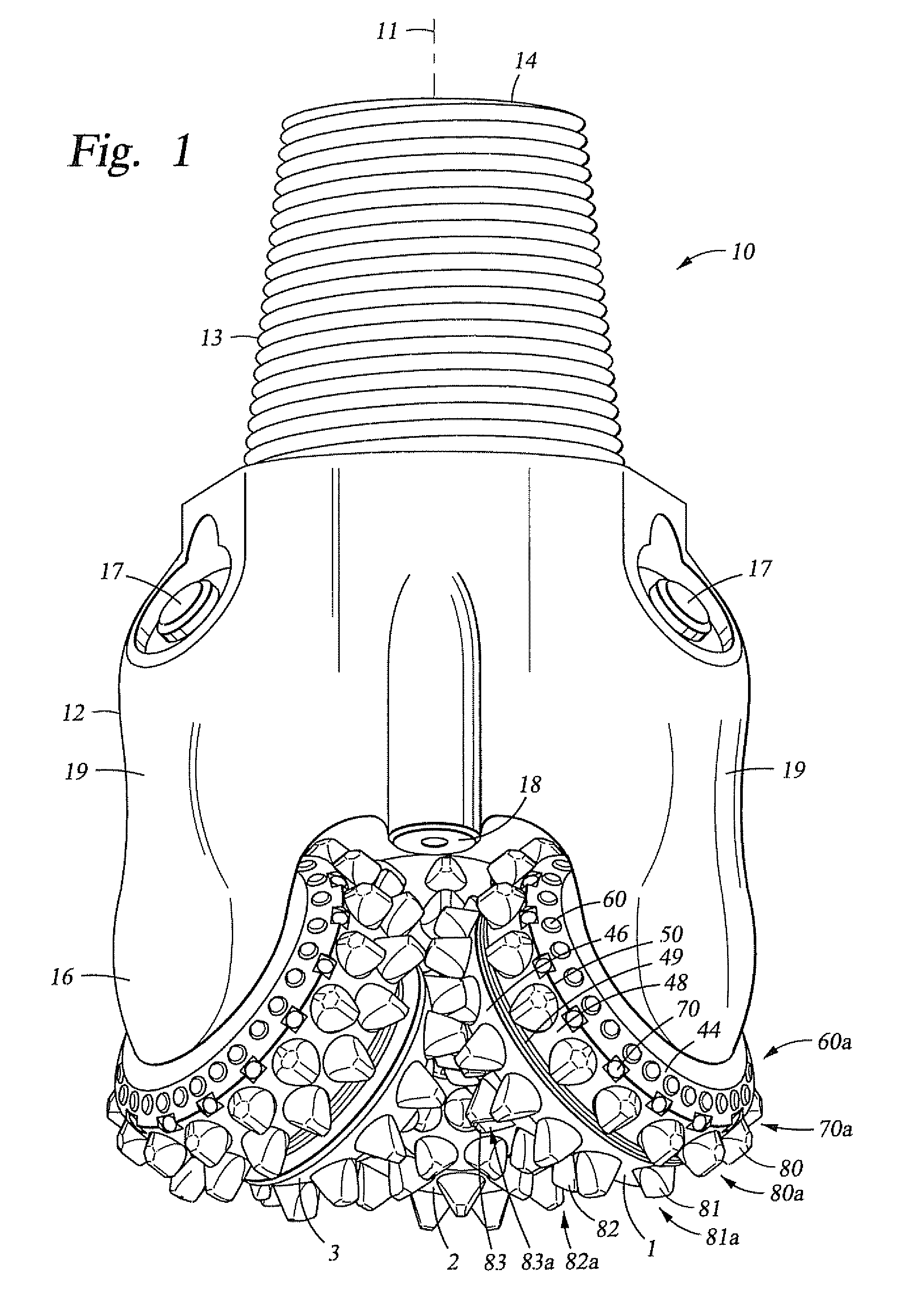
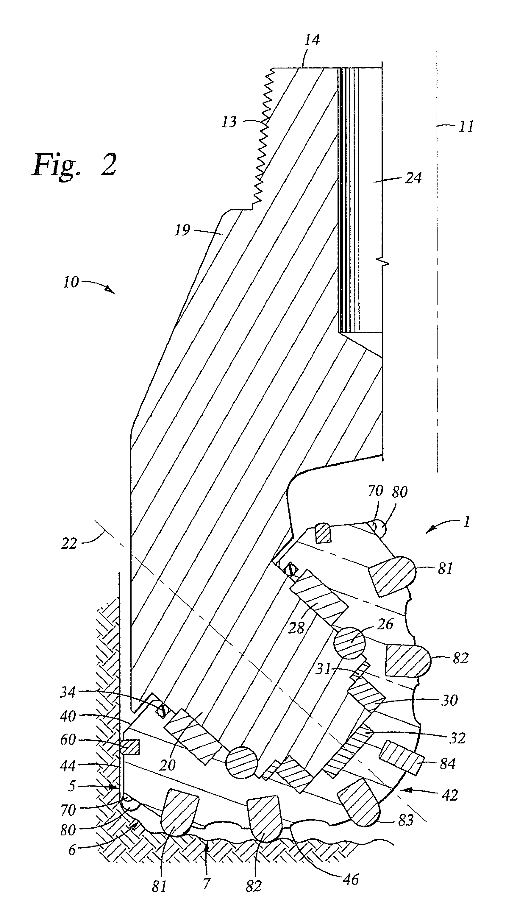
[0016]In accordance with at least one embodiment, a cutter element for a drill bit comprises a base portion having a diameter and a central axis. In addition, the cutter element comprises a cutting portion extending from the base portion and defining an extension height. The cutting portion includes a first pair of flanking surfaces that taper towards one another to form a first elongate chisel crest, and a second pair of flanking surfaces that taper towards one another to form a second elongate chisel crest that intersects the first elongate chisel crest in top view. Further, the first elongate chisel crest defines a first crest tangent angle in front profile view. The first crest tangent angle at 10% of the diameter measured radially from the central axis on the first elongate chisel crest in profile view is greater than 75° and less than or equal to 90°.

[0017]In accordance with other embodiments, a cutter element for a drill bit comprises a base portion. In addition, the cutter e...


PUM


Abstract

A drill bit for cutting a borehole comprises a bit body including a bit axis. In addition, the drill bit comprises a rolling cone cutter mounted on the bit body. Further, the drill bit comprises a cutter element having a base portion with a diameter and a cutting portion extending therefrom. The cutting portion comprising a first pair of flanking surfaces that taper towards one another to form a first elongate chisel crest, and a second pair of flanking surfaces that taper towards one another to form a second elongate chisel crest that intersects the first elongate chisel crest in top view. The first crest tangent angle at 10% of the diameter measured radially from the central axis on the first elongate chisel crest in profile view is greater than 75° and less than or equal to 90°.

Description

CROSS-REFERENCE TO RELATED APPLICATIONS[0001]This application claims benefit of U.S. provisional application Ser. No. 60 / 883,283 filed Jan. 3, 2007, and entitled “Drill Bit With Cutter Element Having Crossing Chisel Crests,” which is hereby incorporated herein by reference in its entirety.STATEMENT REGARDING FEDERALLY SPONSORED RESEARCH OR DEVELOPMENT[0002]Not Applicable.BACKGROUND OF THE TECHNOLOGY[0003]1. Field of the Invention[0004]The invention relates generally to earth-boring bits used to drill a borehole for the ultimate recovery of oil, gas or minerals. More particularly, the invention relates to rolling cone rock bits and to an improved cutting structure and cutter element for such bits.[0005]2. Background Information[0006]An earth-boring drill bit is typically mounted on the lower end of a drill string and is rotated by revolving the drill string at the surface or by actuation of downhole motors or turbines, or by both methods. With weight applied to the drill string, the ...

Claims


Application Information

Patent Timeline
Patent Type & Authority Applications(United States)
IPC IPC(8): E21B10/08
CPCE21B10/52E21B10/16
Inventor SINGH, AMARDEEPBOUDRARE, MOHAMMED
Owner SMITH INT INC
Why Eureka
Try Eureka