System and Method for Humidifying Homes and Commercial Sites

a technology for humidification systems and commercial sites, applied in the direction of heating types, lighting and heating apparatus, separation processes, etc., can solve the problems of reducing the effectiveness and the ability to achieve set point levels, steam tends to require a substantial amount of energy to produce, and the humidity level is not effective and the effect of regulating the humidity level is reliabl

Inactive Publication Date: 2008-07-03
REENS DANIEL J
View PDF39 Cites 30 Cited by
  • Summary
  • Abstract
  • Description
  • Claims
  • Application Information

AI Technical Summary

Benefits of technology

[0016]With a humidification system in accordance with the invention a direct humidification of an air stream is achieved, thus avoiding the drawbacks of by-pass humidifiers while providing a reliable and accurate humidification of the gas stream and thus the areas to which the gas stream is supplied.
[0029]It is still further an object of the invention to provide a humidification system and method for humidifying wherein a humidifying fog is essentially uniformly introduced throughout an air stream so that it can vaporize in a short distance with a minimum of condensation onto walls of the duct in which the air stream flows.

Problems solved by technology

Typically, by-pass humidifiers are activated only during the time that the furnace is operating; thereby failing to provide adequate humidification during off-times of the furnace.
The by-pass humidifiers also only humidify a small percentage of the total air flow that runs through the ductwork, thus reducing their effectiveness and their ability to attain set point levels.
Steam tends to require a substantial amount of energy to produce and its operating costs are, therefore, considerable particularly when generated with electric heaters.
Though these prior art devices may humidify air, they are not necessarily sufficient, both in an operational reliability and economic sense, for the humidification of residences, commercial and zoned facilities.
Also, many of these devices generate a long plume of un-evaporated mist stream, thus requiring a long and large chamber to assure full evaporation and avoid condensation of water onto the walls of the duct.

Method used


Image

  • System and Method for Humidifying Homes and Commercial Sites
  • System and Method for Humidifying Homes and Commercial Sites
  • System and Method for Humidifying Homes and Commercial Sites

Examples


Embodiment Construction

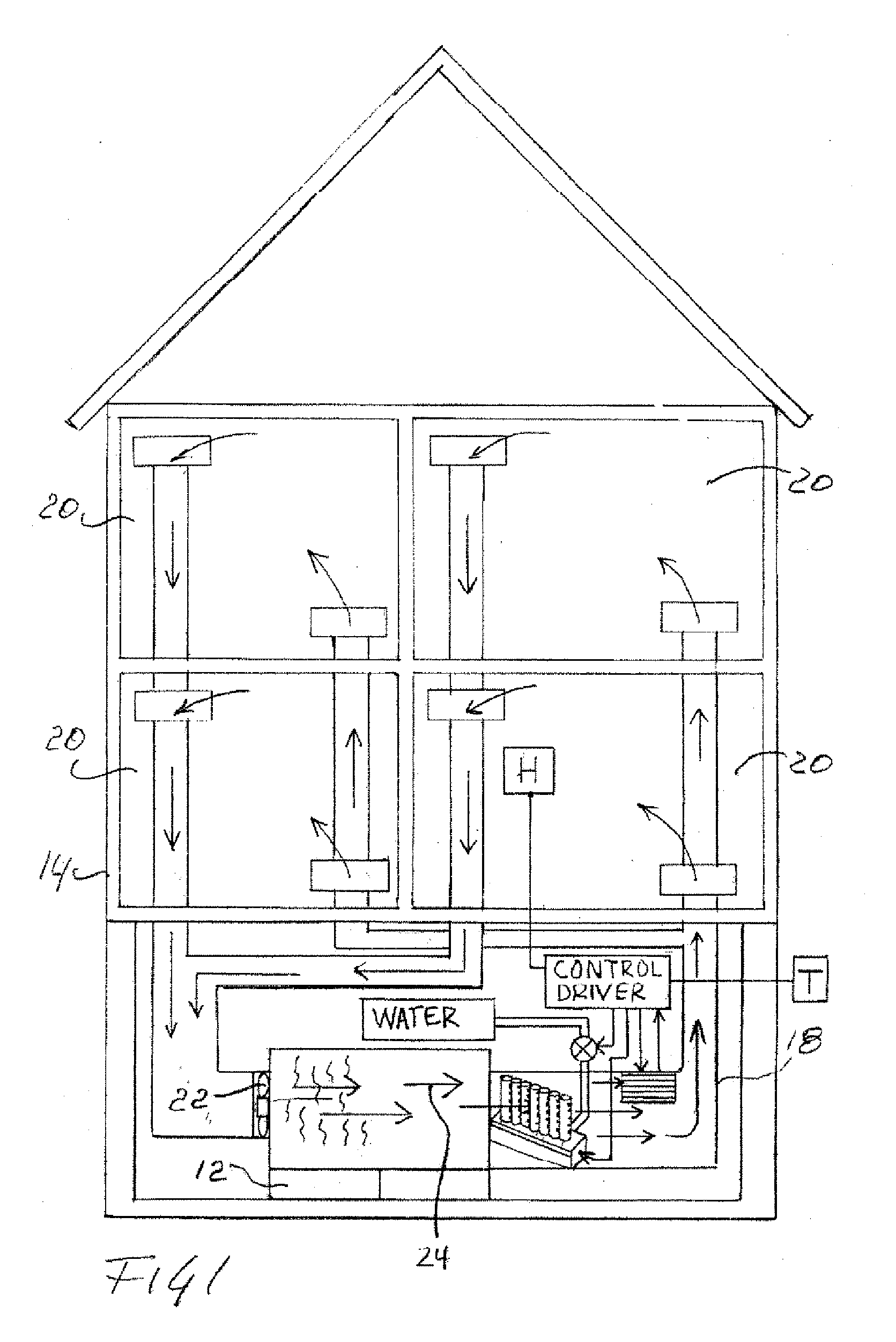
[0051]With reference to FIG. 1 a humidification system 10 in accordance with the invention is shown in place inside a conventional central air system 12 in a residence 14. The humidification system 10 is mounted inside a duct 18 that leads to various rooms 20 in the residence 14. The duct 18 can be a typical duct as is commonly used in a central air system as found in residences or other commercial and industrial facilities. The central air system uses a fan 22 to generate an air stream, as suggested by arrows 24. The air stream is typically heated, with a heater, not shown, and humidified in cold dry weather by system 10. The duct 18 preferably is part of the supply duct though it could also be part of the return duct.

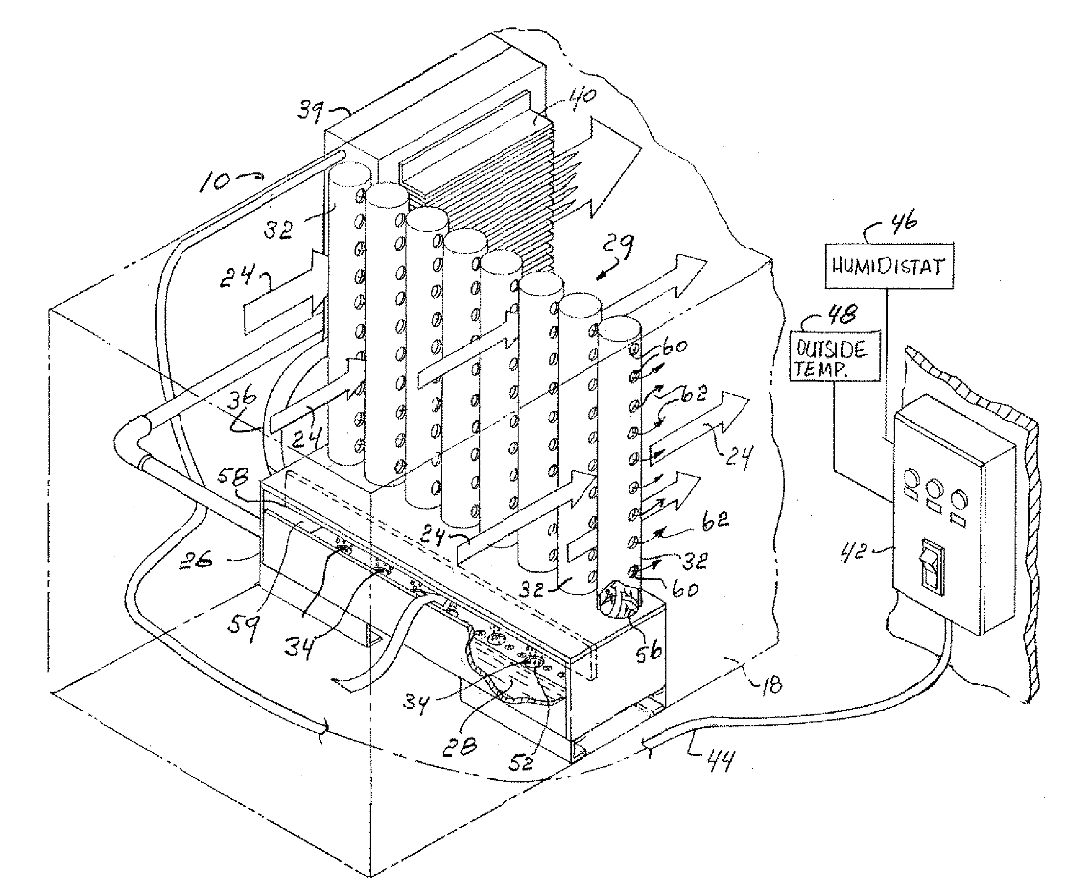
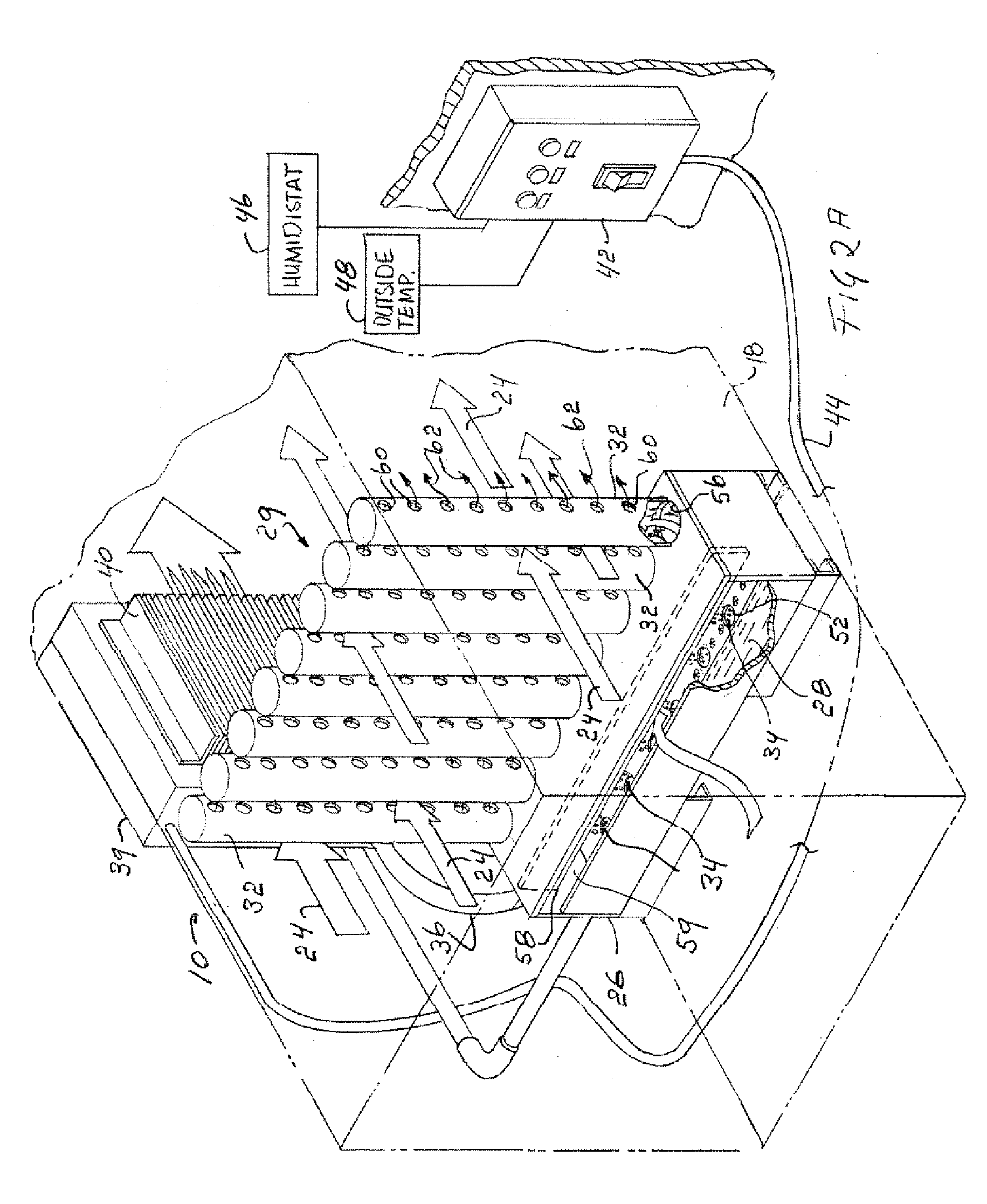
[0052]As shown in FIGS. 2A, and 3 through 9 the humidification system 10 includes a container 26 that holds a shallow reservoir of water 28 having a chamber 30 that communicates with a fog dispersal structure 29 formed with a plurality of hollow dispersal tubes 32 tha...


PUM

PropertyMeasurementUnit
lengthaaaaaaaaaa
lengthaaaaaaaaaa
distanceaaaaaaaaaa

Abstract

Various embodiments are described for humidifying an air stream in a duct are described. In one form the duct is part of a humidification system in a building such as a residence or commercial structure while in another form the duct is part of a standalone unit. The described embodiments use ultrasonic elements for generating a mist composed of droplets and fog and the fog is drawn or pushed by an air stream towards a duct. The duct utilizes a dispersal structure formed of one or a plurality of tubes with openings and distributed at least partly across the duct so that the air stream in the duct can entrain the fog and distribute this in manner whereby the fog can quickly dissipate and evaporate for humidification of the air stream.

Description

PRIOR APPLICATION[0001]This application is a continuation-in-part of U.S. patent application Ser. No. 11 / 082,726 filed on Mar. 17, 2005, currently pending, which in turn claims the benefit of, under Title 35, United States Code, Section 119(e), U.S. Provisional Patent Application No. 60 / 555,473, filed on Mar. 23, 2004, both of which are incorporated by reference herein in their entireties.FIELD OF THE INVENTION[0002]This invention generally relates to a method and apparatus for the humidification of a home or a commercial site or specific zone within a larger facility such as an office or lab or other industrial facility and for the humidification of a process. More specifically this invention relates to the humidification of a moving gas stream, such as air or other gas, and further relates to a control for such humidification.BACKGROUND OF THE INVENTION[0003]The humidification of air streams is well known using various techniques. In accordance with one technique as described in m...

Claims


Application Information

Patent Timeline
Patent Type & Authority Applications(United States)
IPC IPC(8): F24F6/12B01F3/04F24F3/044F24F3/14F24F6/02F24F6/14
CPCF24F6/12Y02B30/80Y10S261/48F24F2006/125Y02B30/70
Inventor REENS, DANIEL J.
Owner REENS DANIEL J
Why Eureka
Try Eureka