Power converting apparatus

Inactive Publication Date: 2008-07-03
MITSUBISHI ELECTRIC CORP
View PDF7 Cites 10 Cited by
  • Summary
  • Abstract
  • Description
  • Claims
  • Application Information

AI Technical Summary

Benefits of technology

[0008]Intended to overcome the aforementioned problems of the prior art, the present invention has as an object the provision of a power converting apparatus which can supply a stable volta

Problems solved by technology

However, if a half-wave rectifier circuit having asymmetrical positive and negative voltage characteristics is connected as a load, for example, positive and negative output voltages of the uninterruptible power supply become unbalanced.
This results in a problem that this type of conventional uninterruptible power s

Method used


Image

  • Power converting apparatus
  • Power converting apparatus
  • Power converting apparatus

Examples


Example

First Embodiment

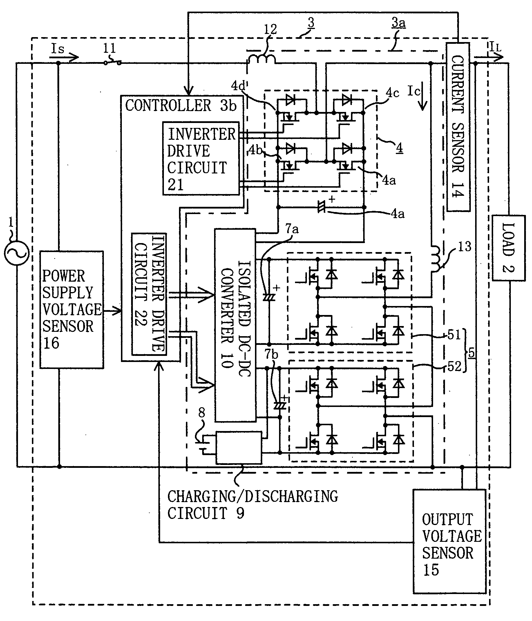
[0023]FIG. 1 is a circuit diagram generally showing the configuration of a power converting apparatus according to a first embodiment of the invention which is used as an uninterruptible power supply 3. As shown in FIG. 1, a main circuit 3a of the uninterruptible power supply 3 which is connected between an AC power supply 1 and a load 2 includes a first power converter 4 made up of a single-phase inverter and a second power converter 5 made up of a plurality of (two in this embodiment) single-phase inverters 51, 52 which are series-connected on an AC output side. An AC output side of the first power converter (single-phase inverter) 4 is series-connected to the AC power supply 1 and the load 2 therebetween, whereas the AC output side of the second power converter 5 is parallel-connected to the AC power supply 1 and the load 2 therebetween via a reactor 13. The first power converter 4 is connected between the AC power supply 1 and the load 2 at a point closer to the ...

Example

Second Embodiment

[0053]FIG. 9 is a circuit diagram generally showing the configuration of a power converting apparatus according to a second embodiment of the invention which is used as an uninterruptible power supply 3, in which elements identical or similar to those of the first embodiment are designated by the same reference numerals. While the uninterruptible power supply 3 of this embodiment is provided with a controller 3b having the same configuration as the first embodiment, the controller 3b is not shown in FIG. 9 for the sake of simplicity.

[0054]Although the first power converter 4 and the second power converter 5 are configured in the same way as in the first embodiment, the first power converter 4 is series-connected to the AC power supply 1 and the switch 11 at a point closer to the load 2 than a point where the second power converter 5 is parallel-connected to the AC power supply 1 and the load 2 in the second embodiment as shown in FIG. 9.

[0055]The uninterruptible pow...


PUM


Abstract

A power converting apparatus used as an uninterruptible power supply connected between an AC power supply and a load includes first and second power converters, a power supply voltage sensor, an output voltage sensor and a controller. The controller calculates rms voltage values of positive and negative half-cycles of an AC output voltage detected by the output voltage sensor, generates a target voltage command based on calculation results and a given reference voltage command, and controls the first power converter based on an output voltage command which is equivalent to a voltage difference between the AC power supply voltage detected by the power supply voltage sensor and the target voltage command.

Description

BACKGROUND OF THE INVENTION[0001]1. Field of the Invention[0002]The present invention relates generally to a power converting apparatus used as a voltage fluctuation compensator or an uninterruptible power supply, for instance, and more particularly, pertains to a power converting apparatus capable of delivering power with a stable voltage regardless of an imbalance between positive and negative voltages.[0003]2. Description of the Background Art[0004]As an example, Japanese Patent Application Publication No. 1999-178216 discloses a conventional uninterruptible power supply which includes a first converter connected between a direct current (DC) power storage device and a load, the first converter being capable of converting power in either a forward or reverse direction, a switch for connecting and disconnecting an alternating current (AC) power supply, and a second converter of which AC output side is series-connected to the AC power source and the switch, the second converter bei...

Claims


Application Information

Patent Timeline
IPC IPC(8): H02J9/00
CPCH02J3/1814H02J3/1857Y02E40/26H02M2001/0093Y02E40/18H02J9/062H02M1/0093Y02E40/10Y02E40/20
Inventor KUITANI, TAKASHIISHII, MUTSUMIAKAGI, MORISHIGE
Owner MITSUBISHI ELECTRIC CORP
Why Eureka
Try Eureka