
Light String of LEDS

a technology of led lights and led strings, applied in the field of led lights, can solve the problems of significant amount of energy consumption and significant amount of heat, and achieve the effects of less electricity, less heat, and energy saving

Inactive Publication Date: 2008-07-03
BEST POINT GROUP LTD
View PDF8 Cites 20 Cited by
  • Summary
  • Abstract
  • Description
  • Claims
  • Application Information

AI Technical Summary

Benefits of technology

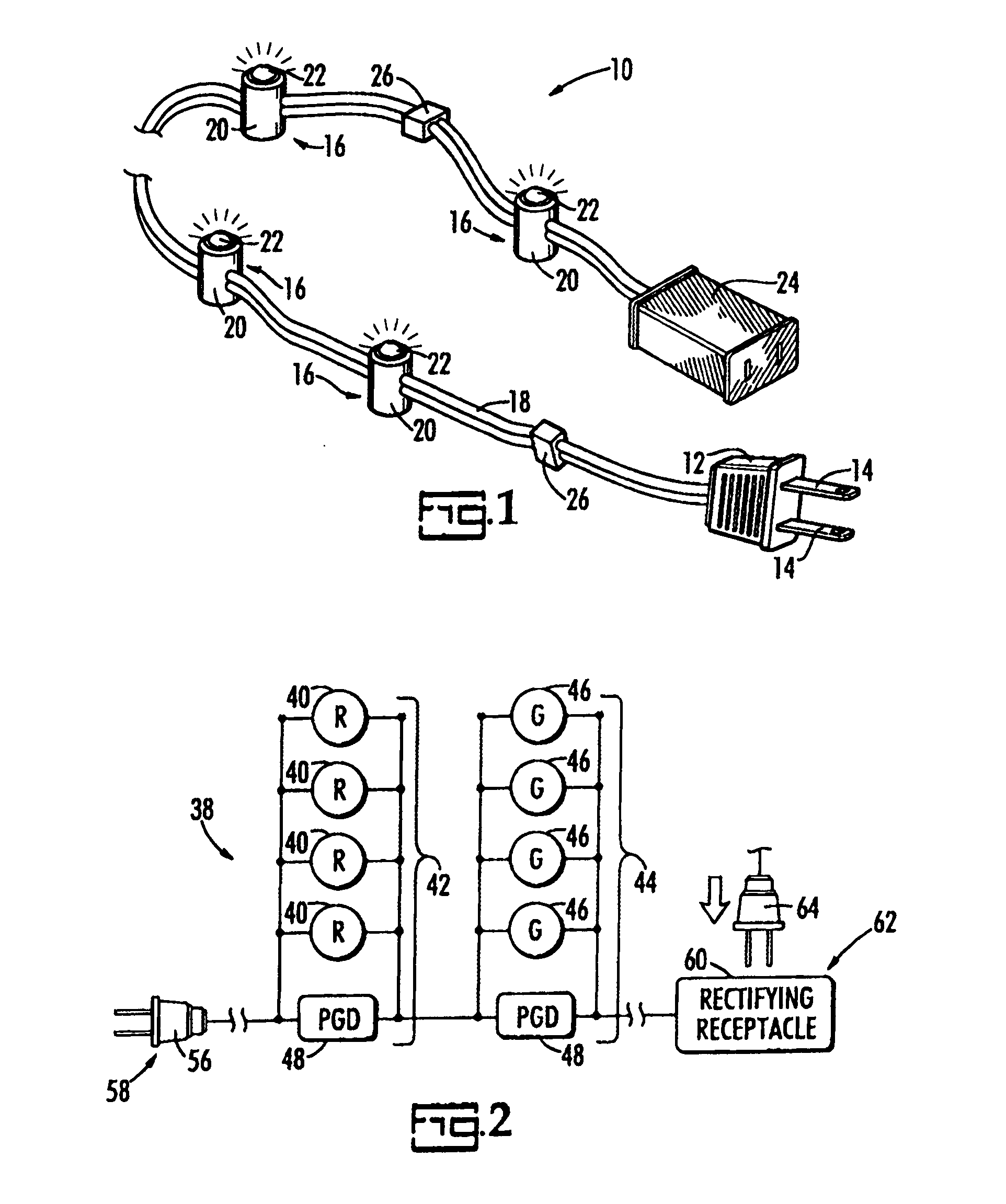
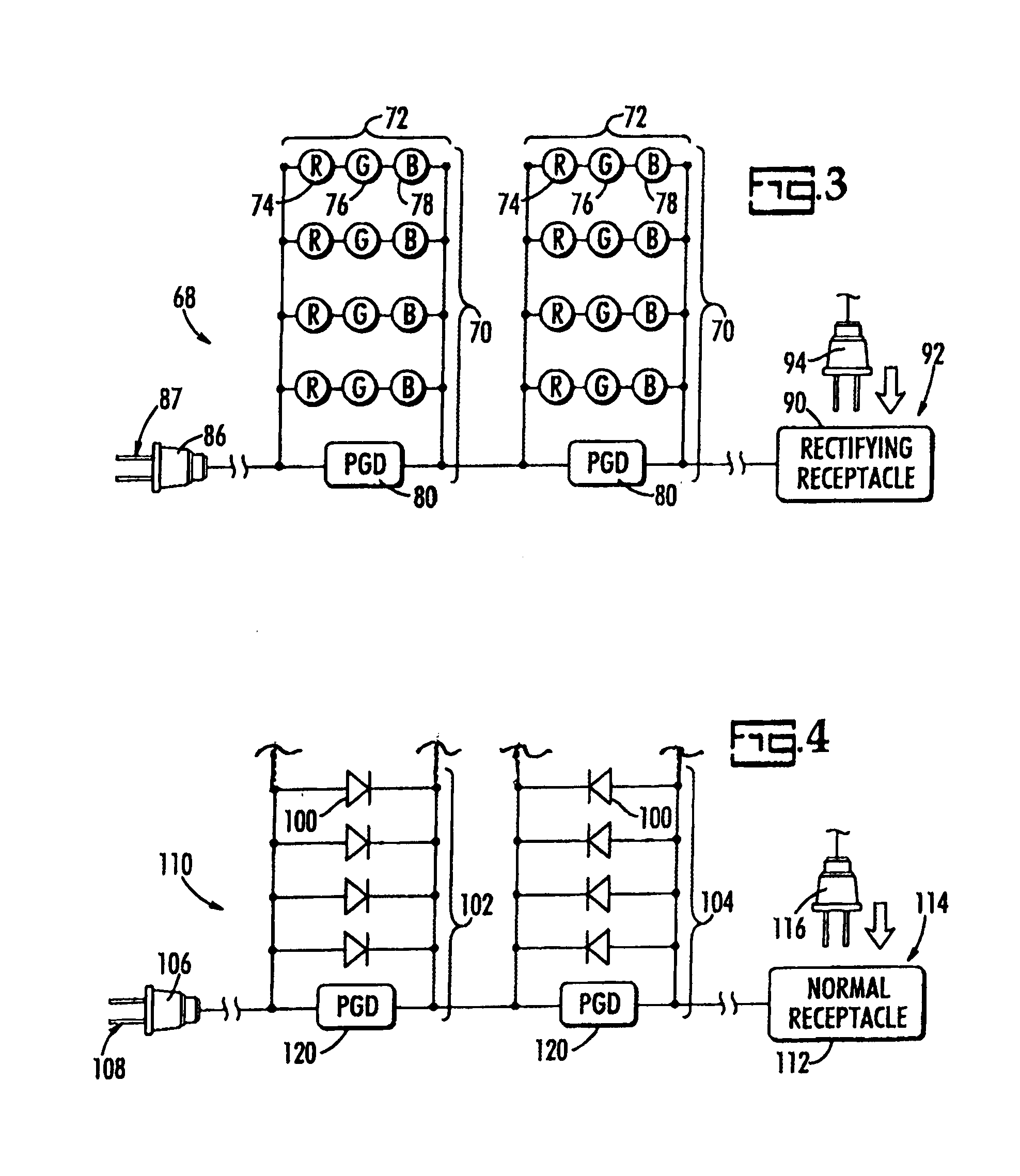
[0011]A particular embodiment of the present invention is a series of groups of LEDs, with each lamp in each group being electrically in parallel with each other LED in the group and with the device for regulating voltage, such as a pair of back-to-back zener diodes. Importantly, the zener diodes are kept in a “partially turned on” mode so that, in the event one of the lights burns out or is removed, it can quickly act to regulate the current flowing in the remaining bulbs.
[0013]A feature of the present invention is that LEDs consume much less electricity and produce much less heat than incandescent lights, with the attendant savings in energy.
[0015]Another feature of the present invention is that the use of LEDs allows a much larger number of lights on each light string.
[0016]Yet another feature of the present invention is the incorporation of the voltage regulator into each group. This feature protects from overcurrent conditions by limiting current to each LED in that group.
[0017]Finally, in prior art LED light strings, resistors are placed in parallel to the LEDs which share electrical current. In the present invention, these resistors are not needed and, accordingly, the energy they consume, in the form of heat, is avoided.

Problems solved by technology

Collectively, they consume significant amounts of energy and produce significants amount of heat.

Method used


Image

  • Light String of LEDS
  • Light String of LEDS
  • Light String of LEDS

Examples


Embodiment Construction

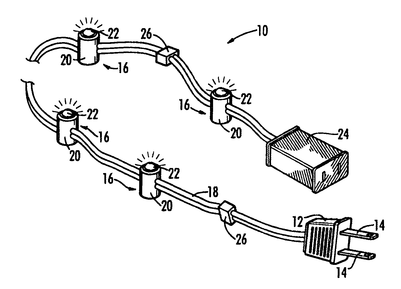
[0024]The present invention is a string of LEDs (light emitting diodes) for use in holiday lighting, and equivalent in function to strings of minilights for example.

[0025]A “string of lights” means a plurality of lights all of which are in electrical connection with each other and with an electrical plug and an electrical receptacle so that, when the plug is connected to a source of electricity, all of the lights light up. The lights of the present string of lights are light-emitting diodes. Light-emitting diodes (LEDs) are solid state, semiconductor devices that emit light of a particular color when a voltage is applied across their terminals. LEDs are diodes so that they conduct electrical current in only one direction and not in the reverse direction.

[0026]Referring now to FIG. 1, there is illustrated in perspective a preferred embodiment of the present invention. A light string 10 includes an electrical plug 12 having two terminals 14 that are insertable into a wall socket (not ...


PUM


Abstract

An LED light string includes series-connected groups of individual LEDs or sets of LEDs, with each LED or set of LEDs in each group being electrically in parallel with each other LED or set of LEDs and with a parallel group device that regulates voltage within the group when LEDs in that group fail. The current to the LEDs is rectified, either in the light string plug or receptacle, preferably the latter. The color of each light in the group, or colors of each set in the group must be the same but successive groups can include LEDs of different colors. In an alternative embodiment, the LEDs can be oriented so that half light on during the first half of an alternating current cycle and the other half light during the second half of an alternating current cycle.

Description

PRIORITY CLAIM [0001]The priority benefit of U.S. provisional patent application Ser. No. 60 / 848,660, filed Oct. 2, 2006, is claimed.BACKGROUND OF THE INVENTION [0002]The present invention relates generally to strings of holiday lighting such as those used for decorating Christmas trees.[0003]Strings of lights, that is, plural lights wired together to be powered from a plug inserted into a wall outlet, are used to decorate Christmas trees and homes. They are used for both interior decorating and exterior decorating.[0004]For a 100-lamp light set, there are typically two types: two series circuits and three series circuits. The light sets both work the same, but the difference between the two is the brightness. One type is normal brightness and the other type is referred to as “super” bright. The difference in lamp brightness is attributable to the lamp voltage. The two series circuits have a lower lamp voltage per lamp (2.5V) i.e. 125 / 50. Each series circuit has 50 lamps.[0005]The t...

Claims


Application Information

Patent Timeline
Patent Type & Authority Applications(United States)
IPC IPC(8): F21S4/00
CPCF21S4/001F21V23/00F21Y2101/02H05B37/04H05B33/0821H05B37/032H05B33/0803F21S4/10F21Y2115/10H05B47/21H05B45/40H05B45/395H05B45/00Y02B20/30H05B47/29
Inventor GIBBONEY, JAMES W.
Owner BEST POINT GROUP LTD
Learn More