
Satellite Dish System and Method

a satellite dish and mounting system technology, applied in the direction of pivotable antennas, collapsible antennas, antennas, etc., can solve the problems of ku-band systems, no current single self-aligning mounting system can be used in all, and a large dish entails greater equipment and service costs

Inactive Publication Date: 2008-07-03
MOBILESAT COMM
View PDF18 Cites 22 Cited by
  • Summary
  • Abstract
  • Description
  • Claims
  • Application Information

AI Technical Summary

Benefits of technology

[0016]In accordance with another aspect of the present invention there is provided a method of aligning a satellite dish comprising the steps of determining satellite elevation in dependence upon geographic position, rotating ...

Problems solved by technology

One of the prohibiting factors of using a Ku-band satellite system, however, is that the farther north a user travels the larger the satellite dish that is required.
A larger dish entails greater expense in both equipment and service, and if the users location must regularly shift over significant distances, such as is the case with some mobile oil rigs, a number of different sized dishes will be required.
However, no current single self-aligning mounting system can be used throughout all of North America with a Ku-band system.
The most consistent complaint of such satellite service customers is that the 1.2 meter systems (which are required for connectivity in Canada) are undesirable, and that the price is too high for the service they are receiving.
It is difficult for customers to accept that they can pay approximately $50 per month for residential high-speed Internet, but need to pay $3000 to $9000 per month for the same type of service at a remote location.
It is understood that it should reasonably cost more, given the remote and temporary setting, but the problem remains.
This fails to address the needs of industries and individuals located or working in remote locations.
As is clear, this is extremely costly.
The rig managers and consultants on the rig sites are normally not satellite technicians and are not trained to set up a satellite dish.
The problem remains, however.
Although Ka-band service is clearly preferable to the standard Ku-band service, the lack of a means to enable self-aligning mobile dish systems renders the Ka-band service undesirable for users in remote, shifting locations.

Method used


Image

  • Satellite Dish System and Method
  • Satellite Dish System and Method
  • Satellite Dish System and Method

Examples


Embodiment Construction

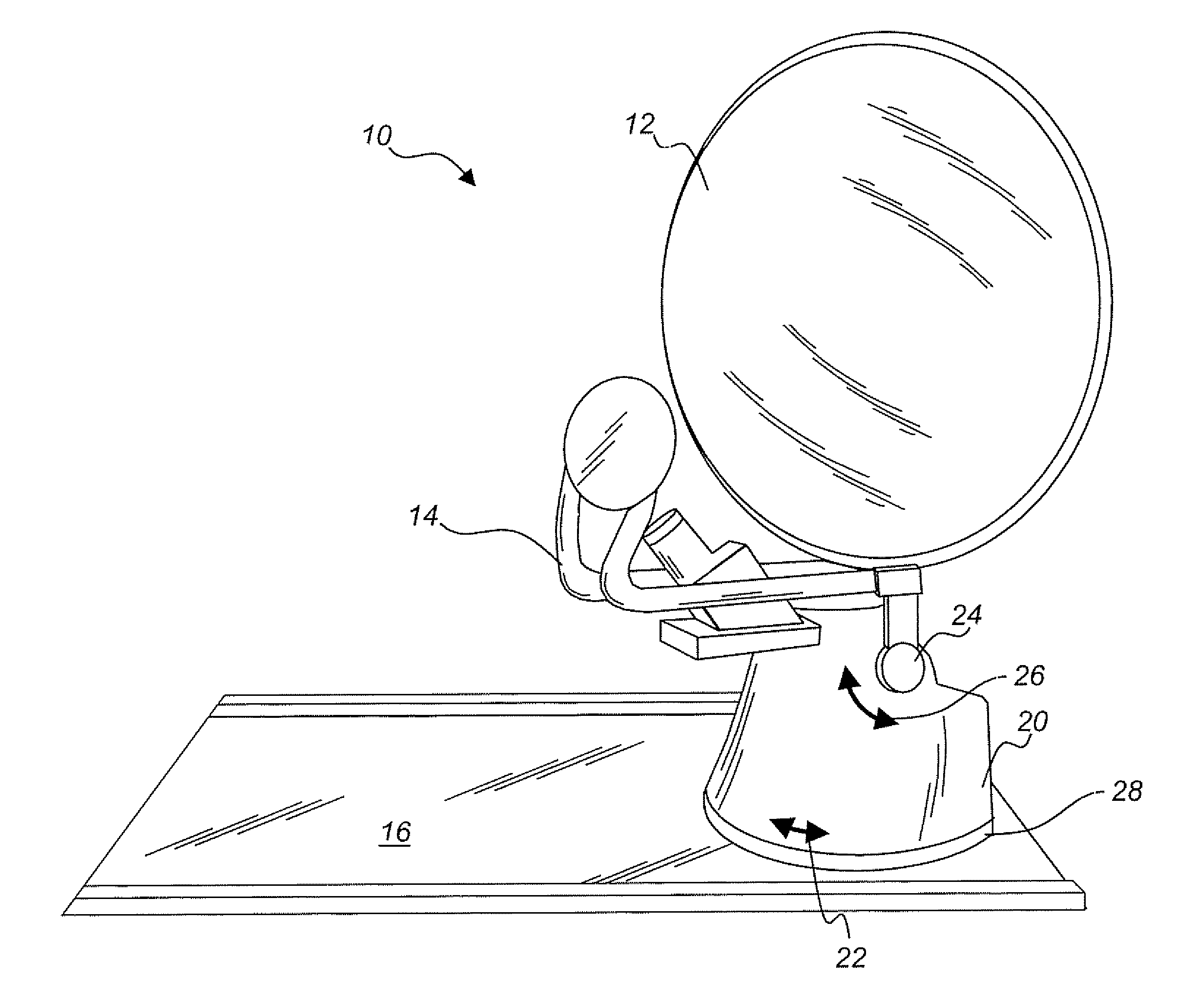
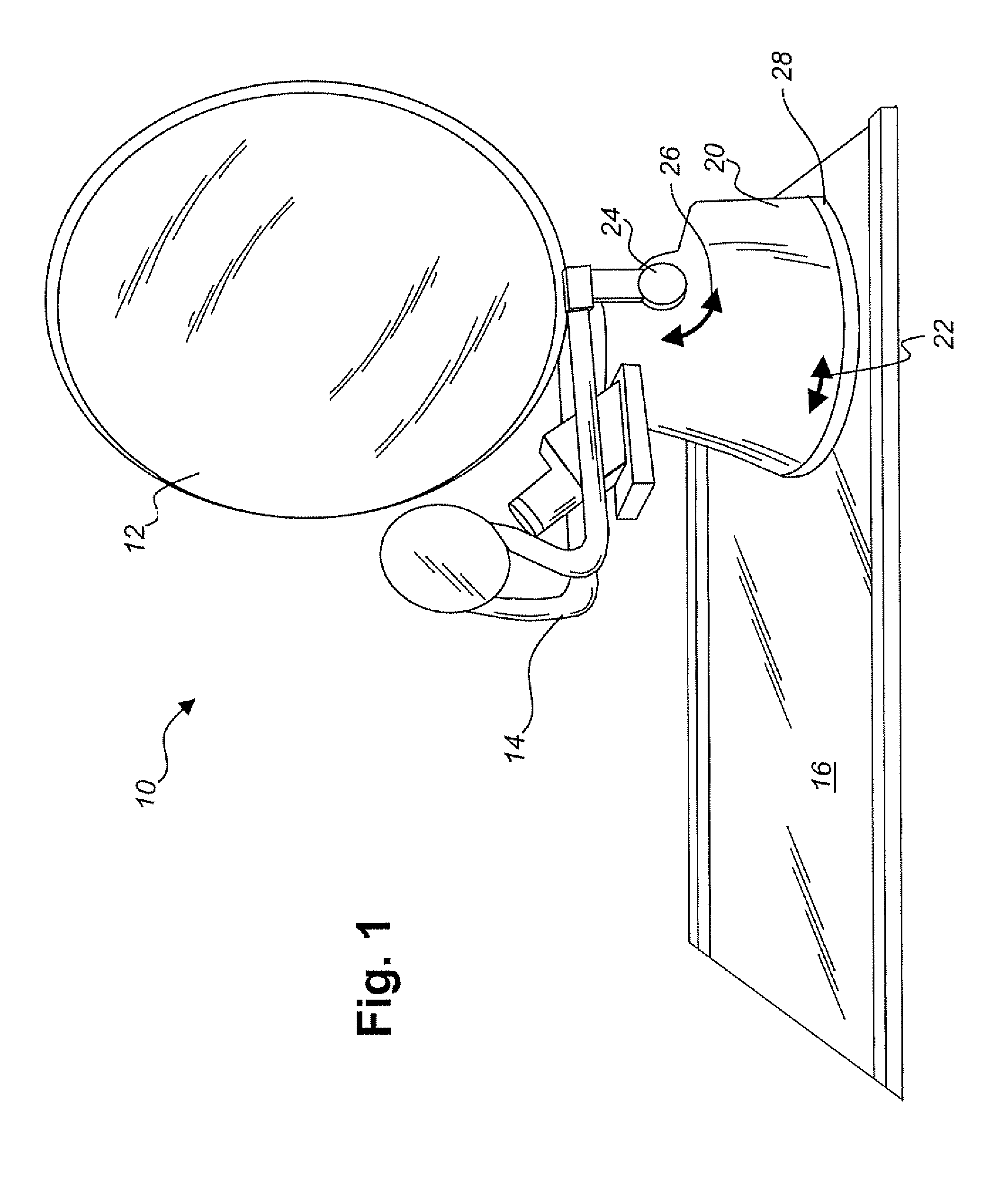
[0025]Referring to FIG. 1 there is illustrated, in a perspective drawing, a satellite dish system in accordance with an embodiment of the present invention. The satellite dish system 10 includes a dish 12 and receiver assembly 14 all mounted on a base 16 via a rotating turret 20. The turret 20 provides for rotational movement, as indicated by arrow 22, of 380 degrees. The dish 12 also pivots on mount 24 from 0 to 90 degrees elevations, as indicated by arrow 26. The rotational movement 22 is facilitated by a Teflon™ skid plate 28.

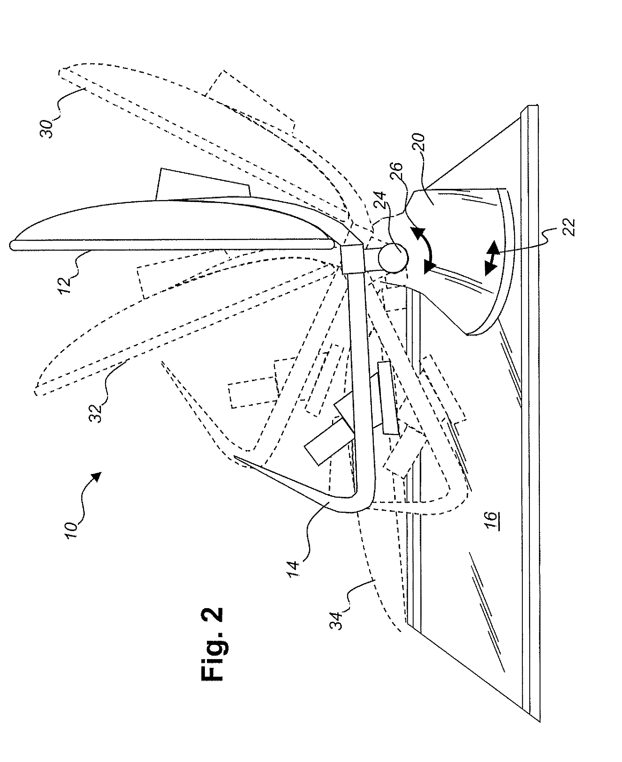
[0026]FIG. 2 illustrates satellite dish system of FIG. 1 moving to its stored position. In FIG. 2, the satellite dish assembly has been rotated to a pre-storage position 30, which is aligned with the base 16. As the dish assembly collapses to its stored position, the receiver assembly 14 touches the base 16 at position 32, then the dish 12 continues to fold to position 34, covering the receiver assembly 14.

[0027]Referring now in detail to FIG. 3, there is il...


PUM


Abstract

There is provided a satellite dish system for comprising a satellite dish mount providing an operable position and a stored position, a controller for effecting position changes for the satellite dish mount and a modem connected to the controller for coupling a computer to a data network via a communications satellite. There is also provided a method of aligning a satellite dish comprising the steps of determining satellite elevation in dependence upon geographic position, rotating the satellite dish at the determined elevation to locate a desired satellite, detecting a signal from the desired satellite and incrementally adjusting rotation and elevation of the satellite dish in dependence upon signal strength.

Description

[0001]This non-provisional application claims benefit to U.S. Provisional Application No. 60 / 812,100.FIELD OF THE INVENTION[0002]The present invention relates to satellite dish systems, and more particularly to alignment of satellite dishes.BACKGROUND OF THE INVENTION[0003]It is well known that satellite systems are employed in the provision of Internet and related services. In particular industries, such as the petroleum industry, which often operate in remote locations and do not have ready access to cable-based Internet systems, the option of using satellite technology is an attractive one.[0004]Previously, only Ku-band satellite service was available worldwide for two-way Internet communication. The providers of such services include DirecWay, Tachyon, Comstream, I-Direct, and ViaSat. One of the prohibiting factors of using a Ku-band satellite system, however, is that the farther north a user travels the larger the satellite dish that is required. For example, south of the 40th ...

Claims


Application Information

Patent Timeline
IPC IPC(8): H01Q3/00G01S5/00
CPCH01Q1/084H01Q3/08H01Q1/3275H01Q1/1257
Inventor ALLEN, JASONLIND, ORRIN THOMASBORGMAN, BENNYBOOTH, DARRELL GRAEME
Owner MOBILESAT COMM
Learn More