
Power-on-reset circuit and method therefor

Inactive Publication Date: 2008-07-03
HIMAX TECH LTD
View PDF4 Cites 13 Cited by
  • Summary
  • Abstract
  • Description
  • Claims
  • Application Information

AI Technical Summary

Benefits of technology

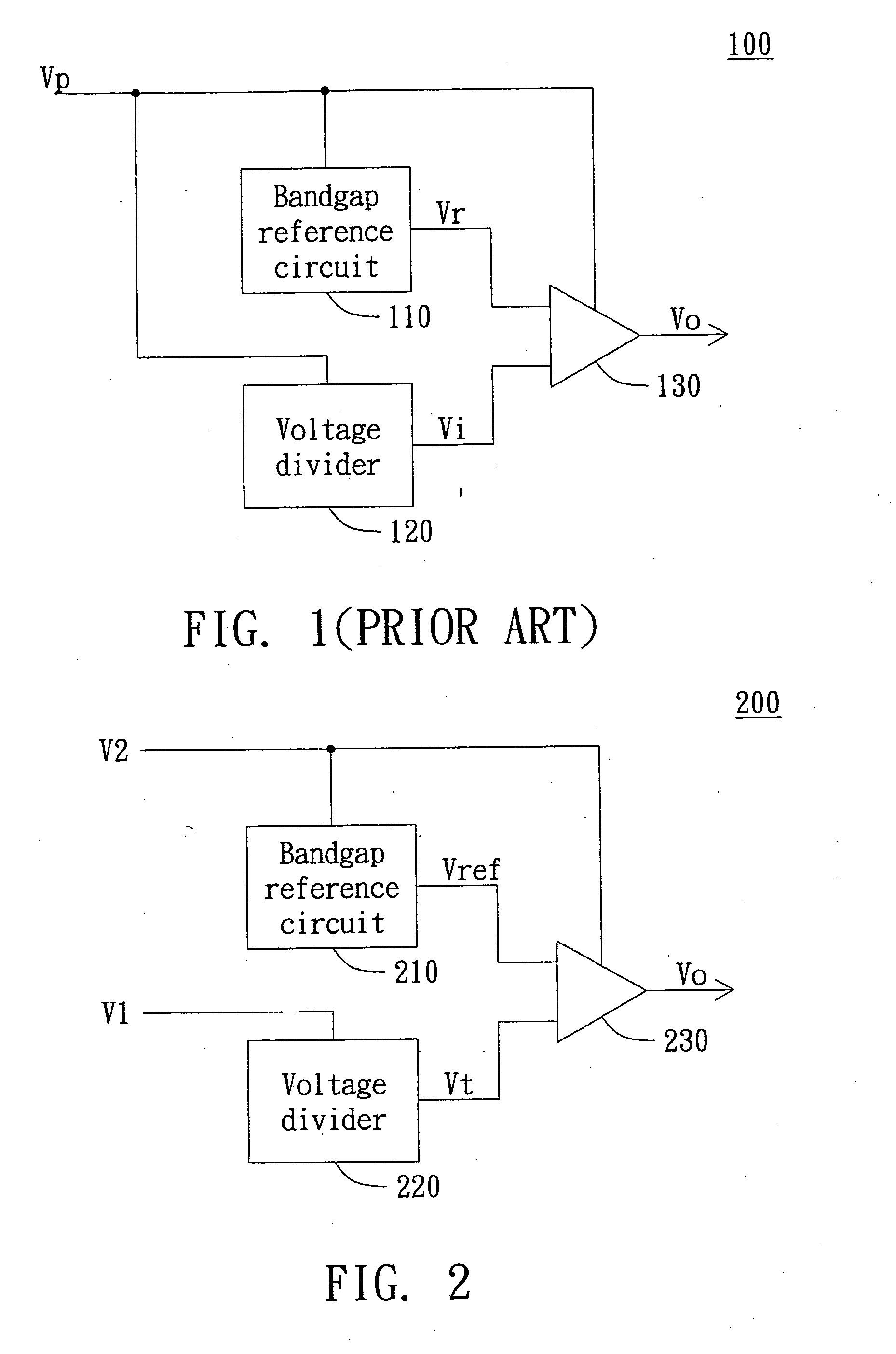
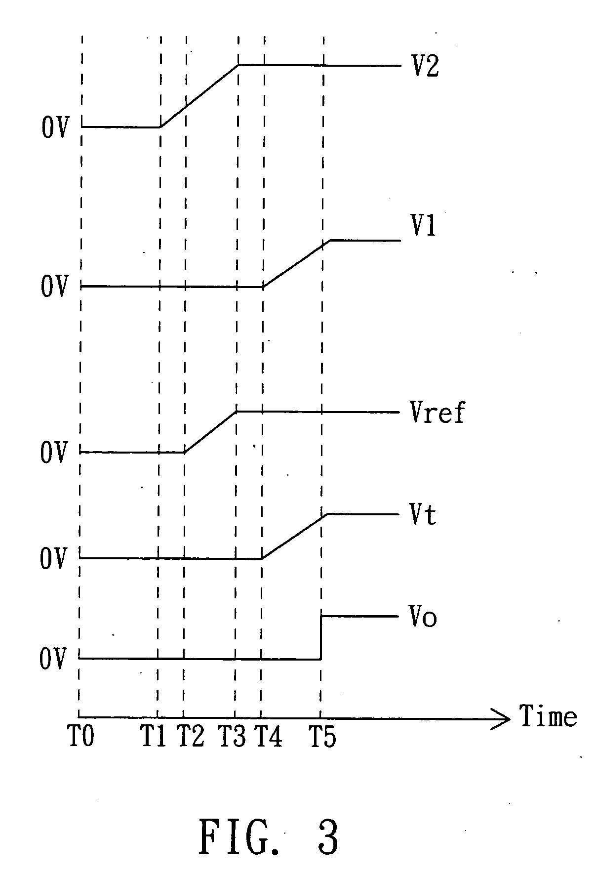
[0007]It is an object of the invention to provide a power-on-reset circuit to reset a semiconductor device within an electric system correctly even when the first supply voltage to power the semiconductor device is not sufficiently large. By sequentially providing a second supply voltage and the first supply voltage to power the bandgap reference circuit and the voltage divider within the power-on-reset circuit, the constant reference voltage may be promptly prepared using the second supply voltage by the time the first supply voltage is generated. Therefore, the comparator may correctly compare the proportional input voltage generated by the voltage divider with the constant reference voltage.

Problems solved by technology

However, the constant reference voltage Vr may not be prepared promptly by the bandgap reference circuit 110 unless the supply voltage Vp is sufficiently large.
Therefore, the conventional power-on-reset circuit is not applicable to low-voltage operations.

Method used


Image

  • Power-on-reset circuit and method therefor
  • Power-on-reset circuit and method therefor
  • Power-on-reset circuit and method therefor

Examples


Embodiment Construction

[0015]The power-on-reset circuit according to an embodiment of the invention is provided to detect a first supply voltage, so as to output a power-on-reset voltage to reset a semiconductor device within an electric system even when the first supply voltage is not sufficiently large. The voltage divider and the bandgap reference circuit of the power-on-reset circuit according to the embodiment of the invention are respectively powered by the first supply voltage and a second supply voltage generated prior to the first supply voltage. Consequently, the constant reference voltage can be promptly prepared by the time the first supply voltage is generated, and the comparator can correctly compare the proportional input voltage with the constant reference voltage to determine whether the first supply voltage is sufficiently large. When the first supply voltage is determined to be sufficiently large by the power-on-reset circuit, the comparator may output the power-on-reset voltage to rese...


PUM


Abstract

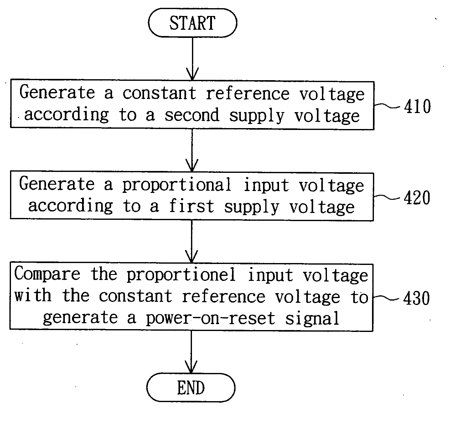
A power-on-reset circuit used to detect a first supply voltage for resetting a semiconductor device within an electric system is provided. The power-on-reset circuit is equipped with the first supply voltage to power the semiconductor device and a second supply voltage generated prior to the first supply voltage. The power-on-reset circuit includes a voltage divider, a bandgap reference circuit and a comparator. The voltage divider is powered by the first supply voltage to generate a proportional input voltage. The bandgap reference circuit is powered by the second supply voltage to generate a constant reference voltage. The comparator compares the proportional input voltage with the constant reference voltage, so as to generate a power-on-reset signal when the proportional input voltage exceeds the constant reference voltage. Therefore, when the first supply voltage is sufficiently large, the power-on-reset circuit can correctly reset the electric system.

Description

BACKGROUND OF THE INVENTION[0001]1. Field of the Invention[0002]The invention relates in general to a power-on-reset circuit, and more particularly to a power-on-reset circuit applicable to low-voltage operations.[0003]2. Description of the Related Art[0004]FIG. 1 is a block diagram of a conventional power-on-reset circuit. The power-on-reset circuit 100 is provided to reset a semiconductor device such as a timing controller within an electric system such as an LCD system according to detection of an supply voltage Vp. When the supply voltage Vp is sufficiently large, the power-on-reset circuit 100 may output a high-level power-on-reset voltage Vo to reset the semiconductor device, otherwise, the power-on-reset circuit 100 may output a low-level power-on-reset voltage Vo to keep the semiconductor device disabled.[0005]The power-on-reset circuit 100 in FIG. 1 includes a bandgap reference circuit 110, a voltage divider 120 and a comparator 130. Both the bandgap reference circuits 110 ...

Claims


Application Information

Patent Timeline
IPC IPC(8): G09G5/00H03L7/00
CPCG09G3/36H03K17/302H03K17/223H03K17/145
Inventor HUANG, CHUNG-MINGHUANG, CHIH-HAUR
Owner HIMAX TECH LTD
Learn More