[0027]The following description is of the best-contemplated mode of carrying out the invention. This description is made for the purpose of illustrating the general principles of the invention and should not be taken in a limiting sense. The scope of the invention is best determined by reference to the appended claims.
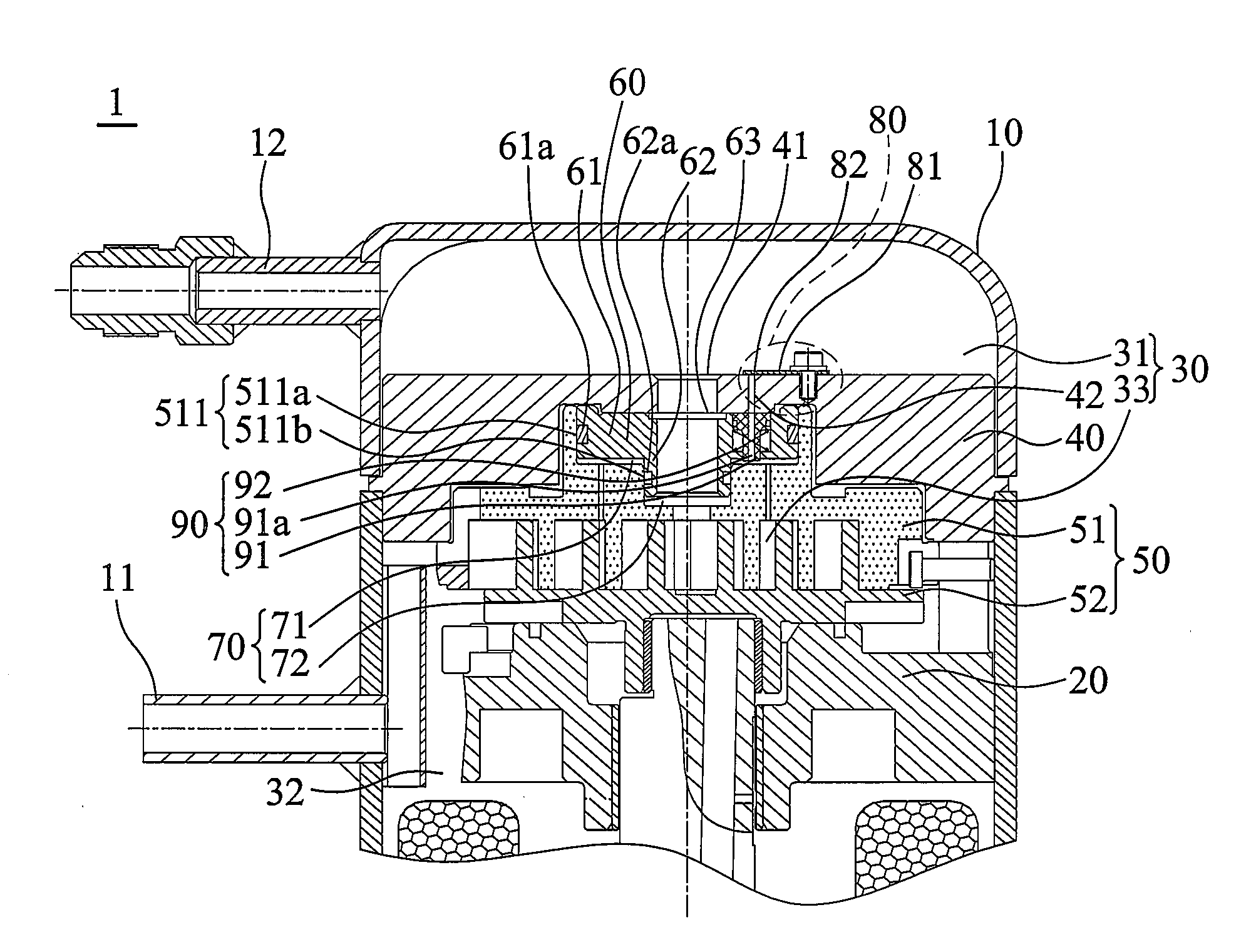
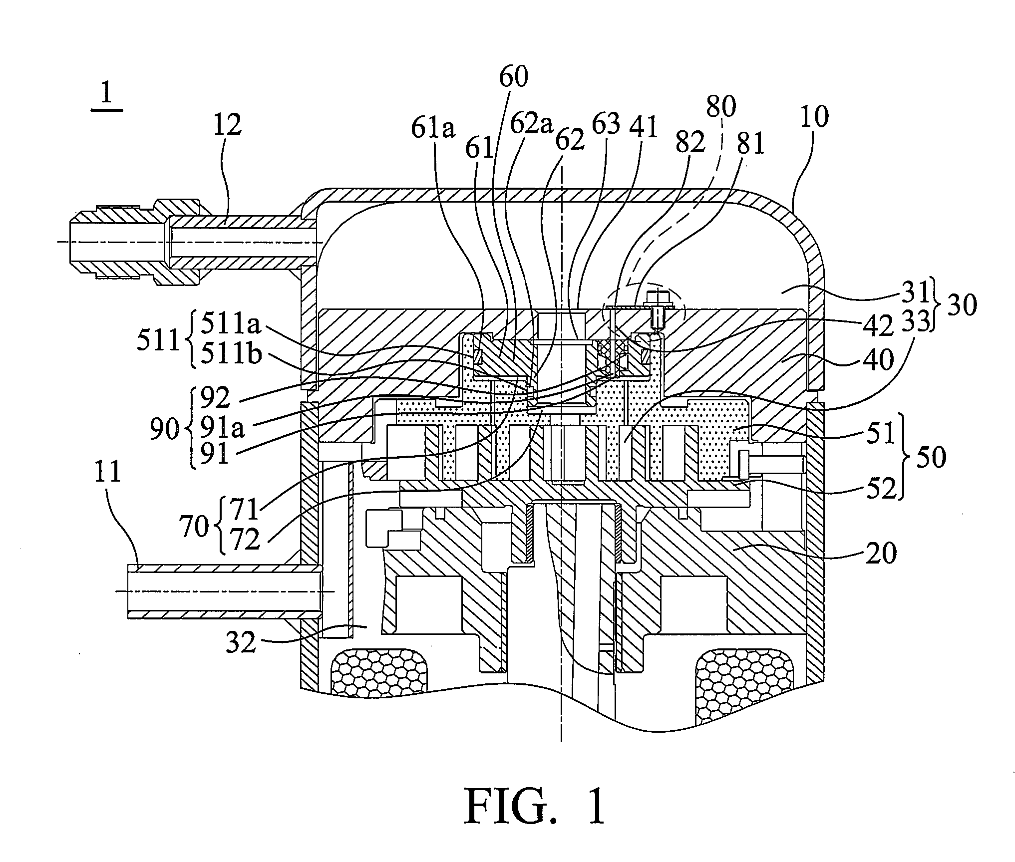
[0028]Referring to FIG. 1, the scroll type compressor 1 comprises a housing 10, a frame 20, a compartment 30, a separator 40, a scroll pairs 50, a slider 60, two compartments 70, at least a pressure-regulating mechanism 80 and a guiding element 90. The housing 10 comprises a flow inlet 11 and a flow outlet 12. The frame 20 is fixed in the housing 10. The compartment 30 is disposed in the housing 10 and separated into a high-pressure compartment 31, a low-pressure compartment 32 and a middle-pressure compartment 33 disposed therebetween. The separator 40 is disposed between the high-pressure compartment 31 and the low-pressure compartment 32, and above the scroll pairs 50. The separator 40 comprises an outlet 41 at the center thereof, and at least a passage 42. The scroll pair 50 comprises a fixed scroll 51 and an orbiting scroll 52. The fixed scroll 51 is engaged with the orbiting scroll disposed between the separator 40 and frame 20. The fixed scroll 51 comprises a space 511 at the top thereof. The space 511 comprises a first chamber 511a and a second chamber 511b. The first chamber 511a is disposed above the second chamber 511b and the diameter of the first chamber 511a is greater than that of the second chamber 511b.
[0029]FIG. 1 shows the slider 60 movably disposed in the space 511 at the top of the fixed scroll 51. The slider 60 comprises a first portion 61 and a second portion 62. The first portion 61 is disposed above the second portion 62. The diameter of the first portion 61 is greater than the diameter of the second portion 62. The first portion 61 comprises an airtight element 61a and the second portion 62 comprises an airtight element 62a. The airtight elements 61a and 62a may be O-rings and are reflectively disposed on the outer edges of the first portion 61 and the second portion 62 preventing air leakage between the slider 60 and space 511. The slider 60 further comprises a hole 63 disposed at the center thereof and connected to the outlet 41. The compartments 70 comprise a first compartment 71 and a second compartment 72. The first compartment 71 is partitioned by the first portion 61 and the first chamber 511a. The second compartment 72 is partitioned by the second portion 62 and the second chamber 511b. The first compartment 71 communicates with the middle-pressure compartment 33. The pressure in first compartment 71 is thus equal to that in the middle-pressure compartment 33.
[0030]The scroll type compressor 1 comprises at least a pressure-regulating mechanism 80 and a guiding element 90. The pressure-regulating mechanism 80 is disposed above the passage 42 and comprises a valve 81 and a retaining element 82 installed above the passage 42 in order. The valve 81 is flexible. The retaining element 82 prevents excessive deformation of the valve 81. The guiding element 90 is disposed in the back of the slider 60 and connected to the first compartment 71. The guiding element 90 comprises a T-shaped element 91 and a flexible element 92. The T-shaped element 91 comprises an air passage 91a connected to the passage 42. The flexible element 92 provides the T-shaped element 91 and the separator 40 seal. When the pressure in the high-pressure compartment 31 is higher than that in the middle-pressure compartment 33, the valve 81 is deformed to tightly seal the passage 42 shown in FIG. 1. Please refer to FIGS. 2 and 3, the pressure-regulating mechanism 80 opens to discharge the air from the middle-pressure compartment 33 to the high-pressure compartment 31 when the pressure in the high-pressure compartment 31 is lower than that in the middle-pressure compartment 33.
[0031]Referring to FIG. 3, when the pressure of air in the outlet 41 decreases, the pressure in the high-pressure compartment 31 is lower than that in the middle-pressure compartment 33. Thus, the compressed airflow discharged from the middle-pressure compartment 33 passes through the air passage 91a of the T-shaped element 91 and the passage 42 of the separator 40, and then enters the high-pressure compartment 31. Finally, the compressed airflow is discharged to outside by the flow outlet 12. Thus, heat loss of the airflow generated by over-compression is averted. Further, load of the scroll type compressor 1 is reduced, improving efficiency.
[0032]FIG. 4 shows an embodiment of the scroll type compressor 1′. The structure of the scroll type compressor 1′ is approximately similar to the scroll type compressor 1 shown in FIGS. 1 to 3. The difference between the scroll type compressor 1′ and the scroll type compressor 1 is that a fixed scroll 51′ of a pair comprising scroll 50′ and orbiting scroll 52′ of the scroll pair 50′ respectively comprise a sealing element 100. Thus, the fixed scroll 51′ and the orbiting scroll 52′ are tightly joined preventing airflow leakage of compressed airflow when the orbiting scroll 52′ revolves around the fixed scroll 51′.
[0033]FIG. 5 shows an embodiment of the scroll type compressor 1″. The structure of the scroll type compressor 1″ is approximately similar to the scroll type compressor 1 shown in FIGS. 1 to 3. The difference between the scroll type compressor 1″ and the scroll type compressor 1 is that the separator 40 further comprises at least a ring pin preventing leakage of the pressurized airflow.
[0034]Note that the number of the pressure-regulating mechanisms 80 and guiding elements 90 are not limited by the above embodiments. The pressure-regulating mechanism 80 and guiding element 90 can be increased in pairs. One pressure-regulating mechanism 80 collocates with one guiding element 90.
[0035]Note that the airtight elements 61a and 62a may be O-rings or other elements according to demand.
[0036]While the invention has been described by way of example and in terms of the preferred embodiments, it is to be understood that the invention is not limited to the disclosed embodiments. To the contrary, it is intended to cover various modifications and similar arrangements (as would be apparent to those skilled in the art). Therefore, the scope of the appended claims should be accorded the broadest interpretation so as to encompass all such modifications and similar arrangements.