Combustion Apparatus

a combustion apparatus and combustion technology, applied in the field of combustion apparatuses, can solve problems such as the total amount of emissions, and achieve the effect of less nox emissions and higher turn down ratio

Inactive Publication Date: 2008-07-03
NORITZ CORP
View PDF14 Cites 17 Cited by
  • Summary
  • Abstract
  • Description
  • Claims
  • Application Information

AI Technical Summary

Benefits of technology

[0051]The combustion apparatus of the present invention produces the primary and the secondary flames in a balanced manner and uniformly distributed throughout the entire area of the combustion site, being practical.
[0052]Further, the combustion apparatus of the present invention achieves a less amount of NOx emissions and a higher Turn Down Ratio. Still further, the combustion apparatus of the present invention is widely adapted to fuel gas having any combustion speed, so as to be used for all types of gas.

Problems solved by technology

Recently, environmental destruction resulting from acid rain has become a grave social issue, and thus, there is a pressing need to reduce a total amount of emission of NOx (nitrogen oxides).

Method used


Image

  • Combustion Apparatus
  • Combustion Apparatus
  • Combustion Apparatus

Examples


Embodiment Construction

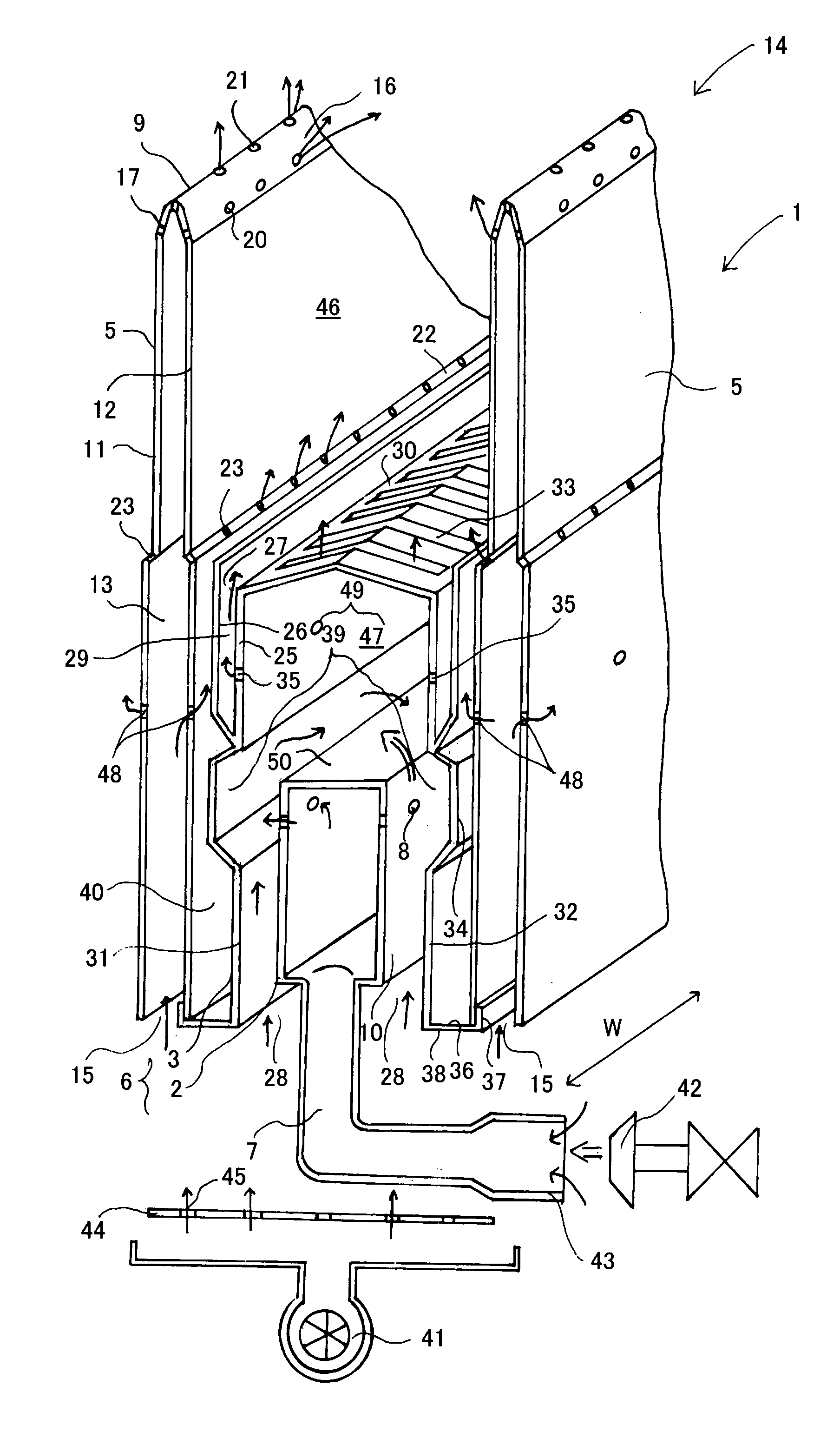
[0077]Now, an embodiment of the present invention will be described below in detail, making reference to the accompanying drawings. First, an outline configuration and basic functions of the present invention will be described, referring to a schematic view of FIG. 1. An embodiment in FIG. 1 conceptually illustrates the present invention.

[0078]In the following descriptions, the vertical positional relationship is based on a combustion apparatus 1 positioned upright and producing flame at an upper part thereof. Terms “upstream” and “downstream” are based on an air or fuel gas flow. A “width direction” denotes a lateral direction (a direction of an arrow “W” in the figure) with a part having the maximal area of the combustion apparatus facing the front.

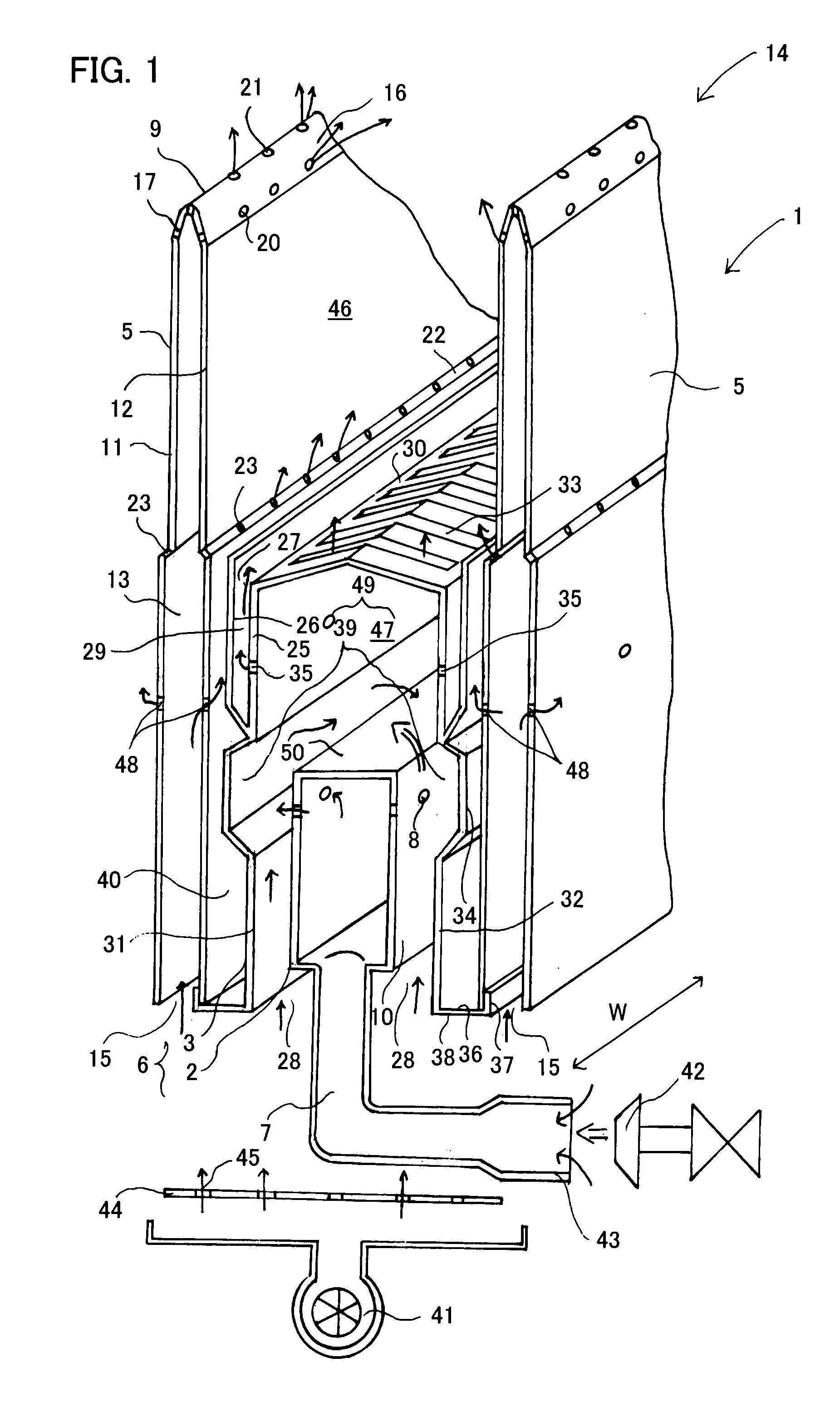
[0079]The combustion apparatus 1 of the present embodiment is used by accommodating more than one apparatus in a casing or alone. The combustion apparatus 1 includes a premixer 2, a burner port assembly 3, and two air passage members 5....


PUM


Abstract

A combustion apparatus 1 includes an intermediate member 6 constituted by a premixer 2 and a burner port assembly 3 and an air passage member 5, the intermediate member 6 being interposed between two air passage members 5. Fuel gas flows into an opening row part 10. The opening row part 10 has a number of openings 8 arranged linearly, so that the fuel gas introduced into the row part 10 is uniformly discharged through each of the openings 8. The fuel gas discharged through the openings 8 of the row part 10 bumps into air at mixing spaces 39. Fuel gas discharged through slots is homogenous and uniform in flow rate. Fuel gas produces a primary flame in a first combustion part 46 to perform a primary combustion. Unburned combustible components are discharged outside through openings of the first combustion part 46 and produce a secondary flame with air supplied through the distal end portion of the air passage member 5.

Description

BACKGROUND OF THE INVENTION[0001]1. Field of the Invention[0002]The present invention relates to combustion apparatuses, and more particularly to a combustion apparatus recommended to be used in a water heater or a bath heater.[0003]2. Description of the Related Art[0004]A combustion apparatus is a main component in a water heater or a bath heater and in widespread use at home as well as at factories.[0005]Recently, environmental destruction resulting from acid rain has become a grave social issue, and thus, there is a pressing need to reduce a total amount of emission of NOx (nitrogen oxides).[0006]There is a combustion apparatus employing a combustion system called the “thick and thin fuel combustion” method adapted to be used in a small device such as a water heater and to reduce NOx emissions.[0007]The “thick and thin fuel combustion” method is designed to produce a main flame from a lean gas mixture composed of fuel gas premixed with air of about 1.6 times the amount of the the...

Claims


Application Information

Patent Timeline
Patent Type & Authority Applications(United States)
IPC IPC(8): F23C5/00
CPCF23C6/045F23D14/085F23D14/045F23C2201/20
Inventor SHIMAZU, MASAHIKOAKIYAMA, TAKASHIWAKADA, TAKESHIXIE, LINHASEGAWA, TAKASHINAGAI, ITSUOWAKATAKE, TAKASHI
Owner NORITZ CORP
Why Eureka
Try Eureka