Biomagnetic field measurement apparatus

Inactive Publication Date: 2008-07-03
KOREA RES INST OF STANDARDS & SCI
View PDF3 Cites 10 Cited by
  • Summary
  • Abstract
  • Description
  • Claims
  • Application Information

AI Technical Summary

Benefits of technology

[0004]It is an object of the present invention to provide a biomagnetic field measurement apparatus, wherein it is inexpen

Problems solved by technology

A conventional biomagnetic field measurement apparatus for measuring a magnetocardiogram has a problem that the apparatus is expensive as many expensive SQUID sensors are required since the SQUID sensors are provided in a matrix of 36 (6×6), 42 (6×

Method used


Image

  • Biomagnetic field measurement apparatus
  • Biomagnetic field measurement apparatus
  • Biomagnetic field measurement apparatus

Examples


Example

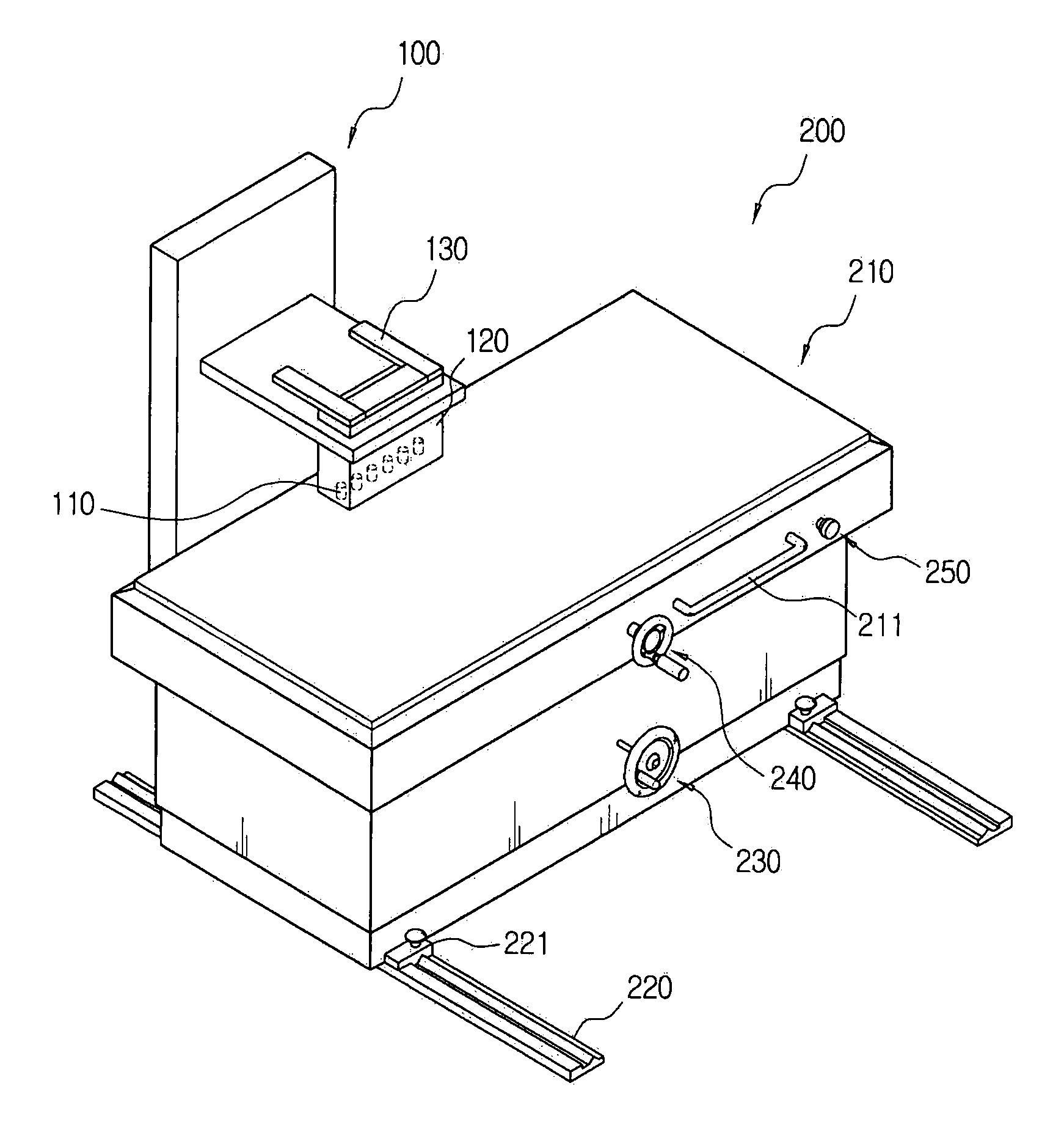
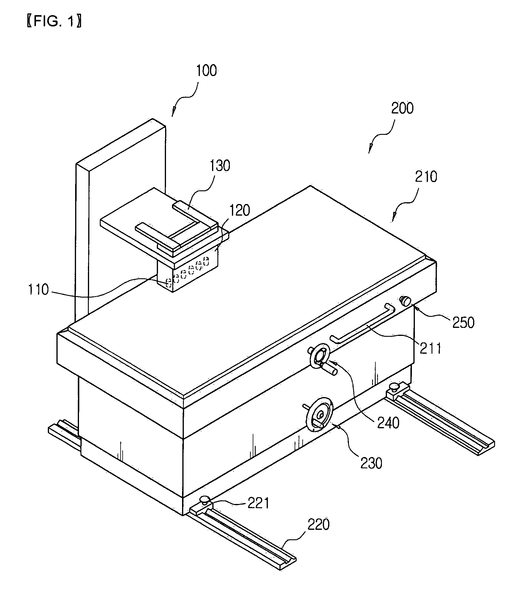
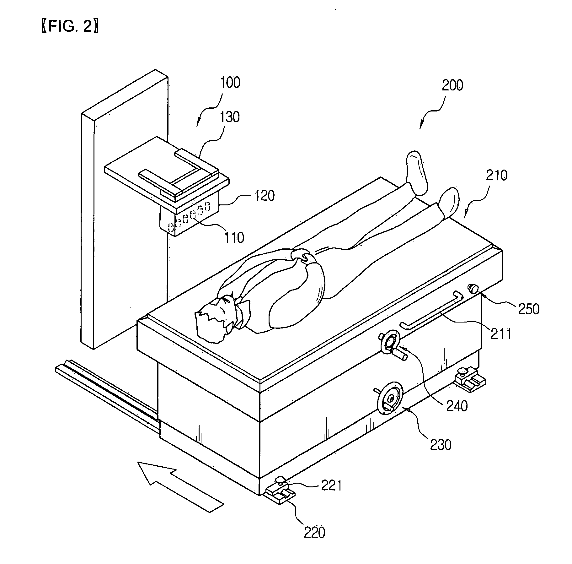
[0012]100: head part[0013]110: SQUID sensor[0014]120: non-magnetic liquid coolant container[0015]130: electronic circuitry part[0016]200: bed part[0017]210: sliding bed[0018]220: sliding rail[0019]230: up and down moving device[0020]240: right and left moving device[0021]250: front and rear moving device

BEST MODE FOR CARRYING OUT THE INVENTION

[0022]Practical and presently preferred embodiments of the present invention are illustrative as shown in the following Examples and Comparative Examples.

[0023]However, it will be appreciated that those skilled in the art, on consideration of this disclosure, may make modifications and improvements within the spirit and scope of the present invention.

[0024]FIG. 1 is a perspective view illustrating a biomagnetic field measurement apparatus according to the present invention, FIG. 2 is a perspective view illustrating a state that a sliding bed of the biomagnetic field measurement apparatus according to the present invention is moved at a state th...


PUM


Abstract

A biomagnetic field measurement apparatus according to the present invention comprises: a head part provided with SQUID sensors (Superconducting Quantum Interference Device) for measuring a magnetocardiogram, the sensors being arranged in a row in a right and left direction at a lower end portion of the head part and being spaced apart by a predetermined space, and a non-magnetic liquid coolant container for cooling the SQUID sensors; an electronic circuitry part for controlling the SQUID sensors and measuring a signal; a signal processing software part for acquiring and storing the signal detected by the electronic circuitry part to a PC, calculating the signal and thus transforming the signal to a magnetic signal or a current signal, then mapping and displaying the transformed signal; and a bed part made of a non-magnetic material, mounted at a lower side of the head part to be spaced apart therefrom and provided with a platy sliding bed for measuring a magnetocardiogram by using the SQUID sensors of the head part at a state that a man to be measured is laid thereon, a sliding rail for allowing the sliding bed to move thereon in a front and rear direction, an up and down moving device for moving the sliding bed, for adjusting a measuring position of the man to be measured, in an up and down direction for adjusting the position of the SQUID sensors of the head part, a right and left moving device for moving the sliding bed in a right and left direction, and a front and rear moving device for moving the sliding bed in a front and rear direction by a predetermined space.
The biomagnetic field measurement apparatus according to the present invention has advantages that since SQUID sensors are arranged in a row and a magnetocardiogram is measured by moving the bed in a predetermined space, it is not necessary for the high-priced SQUID sensors to be provided a lot in comparison with a conventional biomagnetic field measurement apparatus, and thus the apparatus is inexpensive, structurally simple and able to be downsized, a space taken up can be reduced and maintenance thereof is facilitated.

Description

TECHNICAL FIELD[0001]The present invention relates to a biomagnetic field measurement apparatus, and more particularly, to a biomagnetic field measurement apparatus for measuring a magnetocardiogram using a Superconducting Quantum Interference Device (hereinafter briefly referred to as SQUID sensor).BACKGROUND ART[0002]A biomagnetic field is a magnetic signal generated from the heart, brain, spinal cord, stomach, or the like of a human body, and it is possible to measure such biomagnetic field by using a SQUID sensor which is a high sensitivity magnetic sensor. A diagnosis using the biomagnetic field measurement is importantly used in a functional study and functional disease diagnosis of the heart or the like because it is contactless and non-destructive and capable of measuring precisely a minute change in an action current, which is occurred within the heart, on the basis of an excellent time and spatial resolution. Herein, a magnetocardiogram (MGC) measured from the heart repres...

Claims


Application Information

Patent Timeline
IPC IPC(8): G01R33/035
CPCG01R33/0354A61B5/05A61B5/055
Inventor KIM, IN SEONLEE, YONG HOPARK, YONG KI
Owner KOREA RES INST OF STANDARDS & SCI
Why Eureka
Try Eureka