Method and System for Displaying the Electric Field Generated on the Brain by Transcranial Magnetic Stimulation

a transcranial magnetic stimulation and electric field technology, applied in the field of transcranial magnetic stimulation, can solve the problems of difficult, if not impossible, to position the tms coil device, and the objective of using nbs, and achieve the effect of accurate representation of the e-field

Active Publication Date: 2008-07-03
NEXSTIM
View PDF2 Cites 50 Cited by
  • Summary
  • Abstract
  • Description
  • Claims
  • Application Information

AI Technical Summary

Benefits of technology

[0015]In accordance with the present invention, a visualization surface representative of a portion of the brain of a subject at a selected depth is generated by combining an actual representation of the surface of the head of the subject, which is derived from image data representative of the anatomical configuration of the subject's head, with an idealized representation of the head surface, where the combining eliminates or substantially reduces from the visualization surface any protrusions, concavities or other irregularities and provides for an accurate representation of the E-field that would be induced on the brain portion corresponding to the visualization surface by a TMS coil device used to stimulate the brain of the subject. The contribution of each of the actual and idealized representations of the head surface to the combination is a function of the depth of the visualization surface, and the visualization surface resulting from the combination is scaled in size based on the depth of the visualization surface.

Problems solved by technology

Consequently, where the visualization surface includes concavities that correspond to target sites, it is very difficult, if not impossible, to position the TMS coil device so that the maximum E-field is located at the target site on the visualization surface.
Alternatively, if a visualization surface does not closely approximate the shape of the brain, then the regions neighboring a target site likely will not be properly oriented, such that the objective of using NBS to accurately position the TMS coil device in relation to the head, so as to induce a maximum E-field at a target site, becomes unattainable.

Method used


Image

  • Method and System for Displaying the Electric Field Generated on the Brain by Transcranial Magnetic Stimulation
  • Method and System for Displaying the Electric Field Generated on the Brain by Transcranial Magnetic Stimulation
  • Method and System for Displaying the Electric Field Generated on the Brain by Transcranial Magnetic Stimulation

Examples


Embodiment Construction

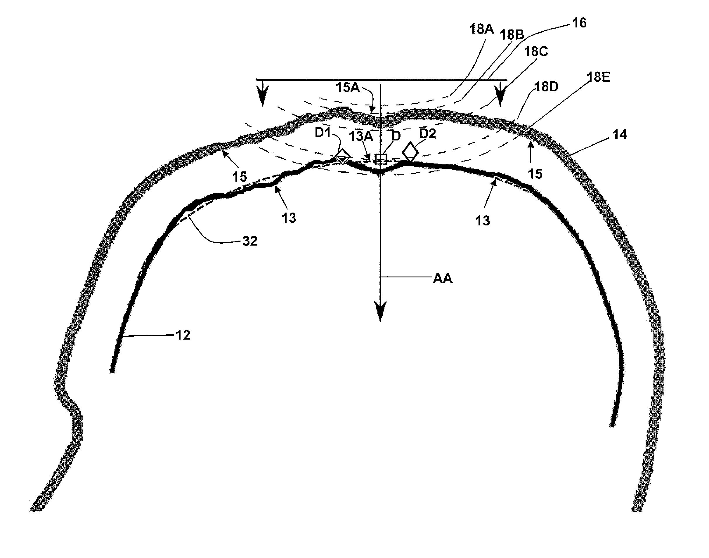
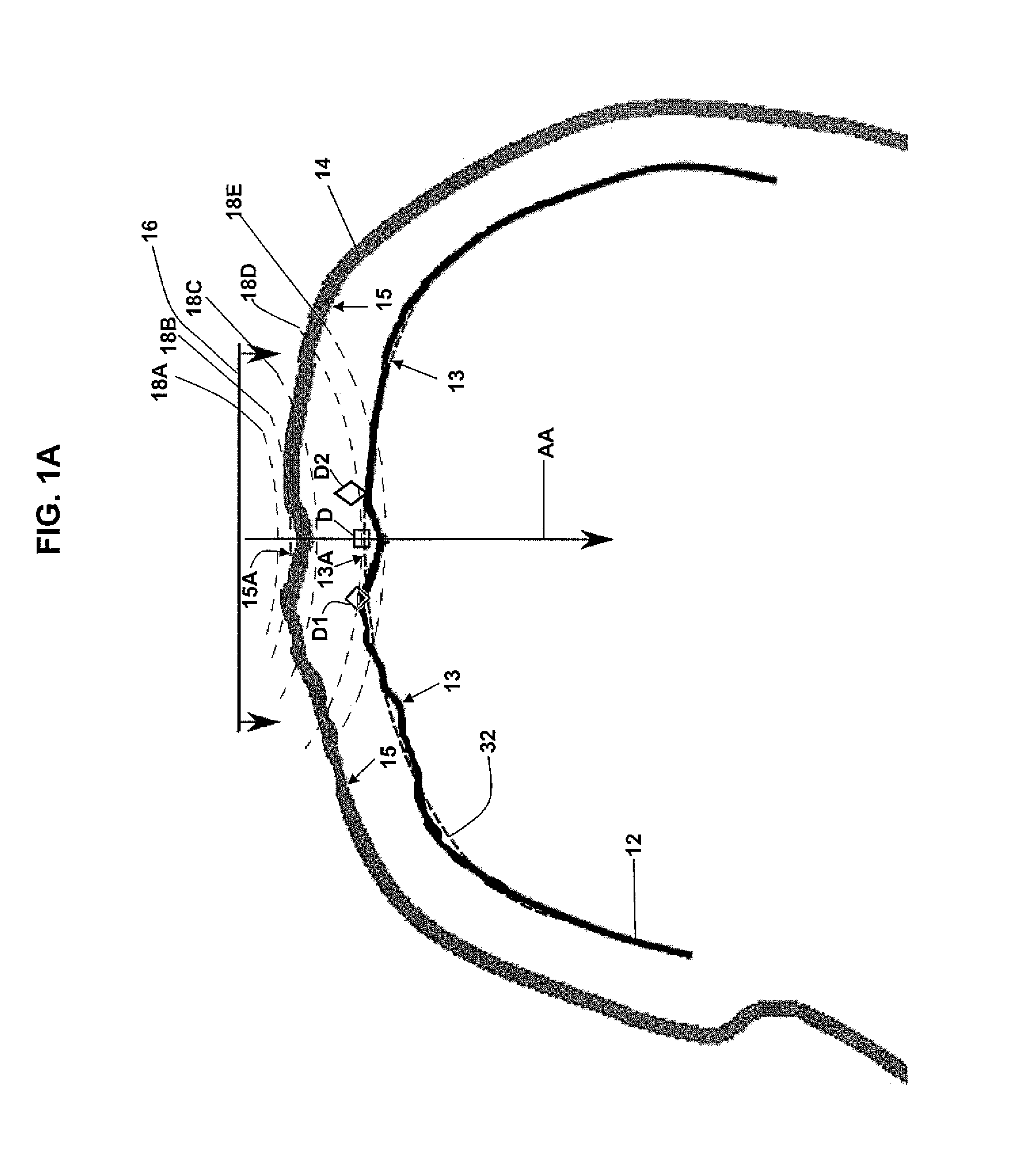
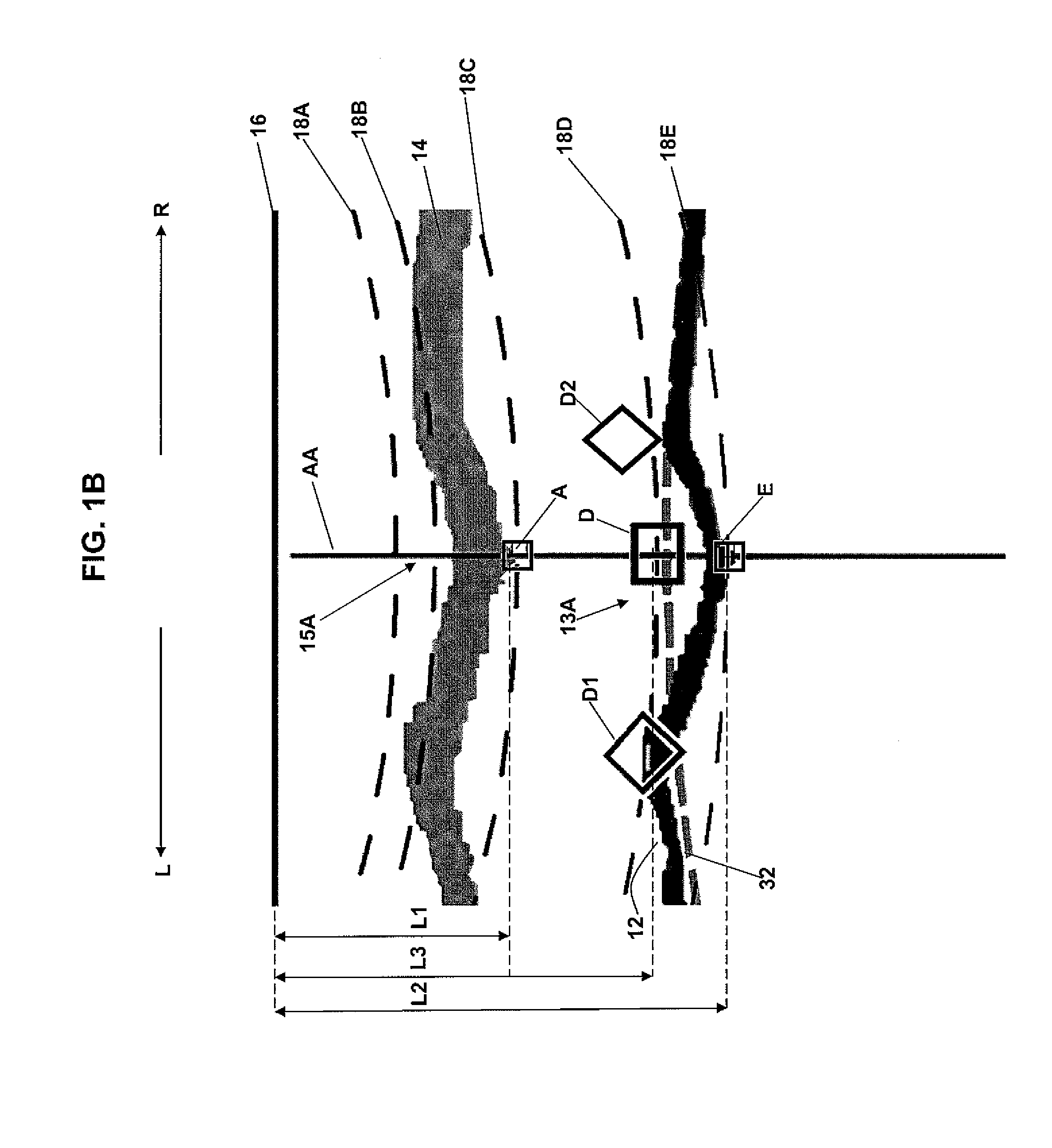
[0027]In NBS, MRI image data representative of the configuration of the anatomy of a subject's head, which has been previously collected, is used to generate a three dimensional (“3D”) image representative of the head and also visualization surfaces representative of portions of the brain at selected depths below the scalp or head surface. The NBS display typically shows a visualization surface overlaid on a 3D image of the head, the position of a TMS coil device being used to stimulate a target site on a portion of the brain in relation to the head surface and the visualization surface, and the E-field induced in a region of the brain surrounding a stimulated target site on the visualization surface.

[0028]In prior art NBS, the configuration of the visualization surface which is generated substantially corresponds to the actual configuration of the head surface of the subject. FIG. 1A shows a cross-sectional view of a typical head 10, a visualization surface 12 of a portion of the b...


PUM


Abstract

A visualization surface representative of a portion of the brain at a depth below the head surface of the subject is generated by combining an actual representation of the head surface with an idealized representation of the head surface. The combining is a function of the depth and is performed to minimize in the visualization surface any irregularities existing in the actual head surface of the subject. A display shows the visualization surface overlaid on a volumetric image of the brain, the electric field induced on a region of the visualization surface by a transcranial magnetic stimulation (“TMS”) induction coil device positioned above the head surface and the TMS coil device. By viewing the display, a user of the TMS coil device can interactively position the TMS coil device in relation to the head surface and, for a target site on the brain at a selected depth, determine the position at which the TMS coil device induces a maximum E-field on a visualization surface corresponding to the selected depth.

Description

CROSS REFERENCE TO RELATED APPLICATION[0001]This application claims the benefit of U.S. Provisional Application No. 60 / 825,454 filed Sep. 13, 2006, assigned to the assignee of this application and incorporated by reference herein.FIELD OF THE INVENTION[0002]The present invention relates generally to transcranial magnetic stimulation and, more particularly, to displaying an accurate representation of the electric field induced on the brain of a subject by a transcranial magnetic stimulation induction coil device.BACKGROUND OF THE INVENTION[0003]Transcranial magnetic stimulation (“TMS”) uses an induction coil in which a time-varying magnetic field is generated to induce an electric field (“E-field”) within the brain. The neurons at the locations of the brain exposed to a strong enough E-field will become activated, or stimulated. In navigated brain stimulation (“NBS”), the E-field induced in the brain by a TMS induction coil device is shown as an overlay on a graphical display of an a...

Claims


Application Information

Patent Timeline
Patent Type & Authority Applications(United States)
IPC IPC(8): A61N2/02
CPCA61N2/004A61N2/02G06T2210/41G06T19/00A61N2/006G06T17/20
Inventor HURME, RAINEAUTIO, ILKKASIPILA, PERTTURUOHONEN, JARMO
Owner NEXSTIM
Why Eureka
Try Eureka