Power transmission apparatus and rotation apparatus

a technology of power transmission apparatus and rotating apparatus, which is applied in the direction of wing accessories, machine supports, gearing, etc., can solve the problems of damage to the motor, difficulty in obtaining high torque levels, and the degree of deceleration, and achieve high torque and high deceleration

Inactive Publication Date: 2008-07-10
SAMSUNG ELECTRO MECHANICS CO LTD
View PDF5 Cites 9 Cited by
  • Summary
  • Abstract
  • Description
  • Claims
  • Application Information

AI Technical Summary

Benefits of technology

[0008]An aspect of the invention is to provide a power transmission apparatus and a rotation apparatus, which ca

Problems solved by technology

Thus, as the high rotational speed of the motor has to be reduced to several to several tens of revolutions per minute, a sufficient degree of deceleration may not be achieved with only a gear module, and it may be difficult to obtain high levels of torque

Method used


Image

  • Power transmission apparatus and rotation apparatus
  • Power transmission apparatus and rotation apparatus
  • Power transmission apparatus and rotation apparatus

Examples


Embodiment Construction

[0024]The power transmission apparatus and rotation apparatus according to certain embodiments of the invention will be described below in more detail with reference to the accompanying drawings, in which those components are rendered the same reference numeral that are the same or are in correspondence, regardless of the figure number, and redundant explanations are omitted.

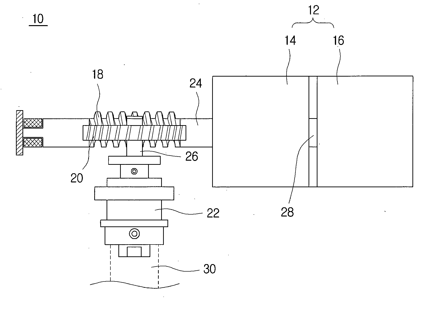
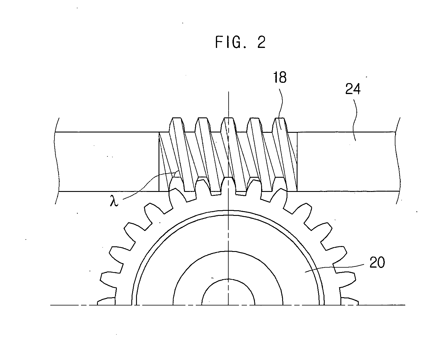
[0025]FIG. 1 is a cross-sectional view of a power transmission apparatus according to an embodiment of the invention. In FIG. 1 are illustrated a power transmission apparatus 10, a power generating part 12, a motor 16, a gear module 14, a worm 18, a worm gear 20, a friction hinge 22, a main axis 24, an output axis 26, a drive axis 28, and a rotational axis 30.

[0026]The power generating part 12 may be such that provides a rotational force to the drive axis 28, and may employ various apparatus known to those skilled in the art. For example, the rotational force may be provided using a belt and pulleys, or may be p...


PUM


Abstract

A power transmission apparatus and a rotation apparatus are disclosed. A power transmission apparatus that includes: a power generating part, which includes a drive axis; a worm, which is joined to the drive axis; a worm gear, which meshes with the worm, and which includes an output axis configured to transmit power; and a friction hinge, which is joined to the output axis, and which is configured to engage and disengage a rotational force of the output axis, can provide sufficiently high deceleration and high torque, even when a low-capacity motor having a low cogging torque is used. Also, the power transmission apparatus can be made safer and less noisy for not only automatic operation by the motor but also manual operation by a user, while the gear module, motor, etch, can be protected from excessive loads.

Description

CROSS-REFERENCE TO RELATED APPLICATIONS[0001]This application claims the benefit of Korean Patent Application No. 10-2007-0001974 filed with the Korean Intellectual Property Office on Jan. 8, 2007, the disclosure of which is incorporated herein by reference in its entirety.BACKGROUND[0002]1. Technical Field[0003]The present invention relates to a power transmission apparatus and a rotation apparatus.[0004]2. Description of the Related Art[0005]A gear module joined to a motor may serve to reduce the rotational speed transferred from the motor by a particular rate. Multiple gears can be arranged in a gear module, with the rotation of the motor decelerated by the combination of these gears.[0006]Rotating a mass such as a television or computer monitor, however, requires high torque, although a high rotational speed may not be necessary. Thus, as the high rotational speed of the motor has to be reduced to several to several tens of revolutions per minute, a sufficient degree of decelera...

Claims


Application Information

Patent Timeline
IPC IPC(8): F16H1/16E05F15/10
CPCE05D11/087E05Y2900/606F16H1/16F16M11/08E05F15/614F16M11/2014F16M13/02Y10T74/18792F16M11/18F16H1/00
Inventor CHOI, DONG-WONLEE, CHIL-SUNGKIM, JAE-KYUNGKIM, JAE-HUNPARK, KYOUNG-SHIN
Owner SAMSUNG ELECTRO MECHANICS CO LTD
Why Eureka
Try Eureka