Led Lighting Apparatus in a Plastic Housing

a technology of plastic housing and led lighting, which is applied in the direction of lighting heating/cooling arrangements, lighting protection devices, lighting applications, etc., can solve the problems of high cost and therefore infrequent appearance, damaged seals of the sealing arrangements of exposed windows, and easy corrosion and leakage of exposed window sealing arrangements, etc., to achieve high impact strength and high strength

Active Publication Date: 2008-07-10
AMOR GRANT HAROLD +1
View PDF29 Cites 40 Cited by
  • Summary
  • Abstract
  • Description
  • Claims
  • Application Information

AI Technical Summary

Benefits of technology

[0007]It is an object of the present invention to provide a lighting apparatus which addresses one or more of the above problems.

Problems solved by technology

Accordingly, globes are often not replaced until the boat is raised from the water, which is a costly and therefore infrequent occurrence.
However, such lights usually have an exposed window sealing arrangement that can be prone to corrosion and leakage.
This is necessary since without the cooling effect of the water, seals of the sealing arrangements of such lights can be damaged by the heat of the lights.
As a result, when used on boats, it is necessary to turn the lights off when the boat is planing since the lights invariably rise out of the water.
The window assembly is relatively complicated in its construction and can be prone to leakage when the seal wears out.
Furthermore, since the housing is electrically conductive it can cause galvanic corrosion of itself or a mounting plate or wall if such components are also of metal.
It will be appreciated that since glass is inherently brittle, it can be damaged, at least by cracking, when exposed to impact.
As a result, presently available lights mounted in public areas are often damaged by vandals or environmental conditions.

Method used


Image

  • Led Lighting Apparatus in a Plastic Housing
  • Led Lighting Apparatus in a Plastic Housing
  • Led Lighting Apparatus in a Plastic Housing

Examples


Embodiment Construction

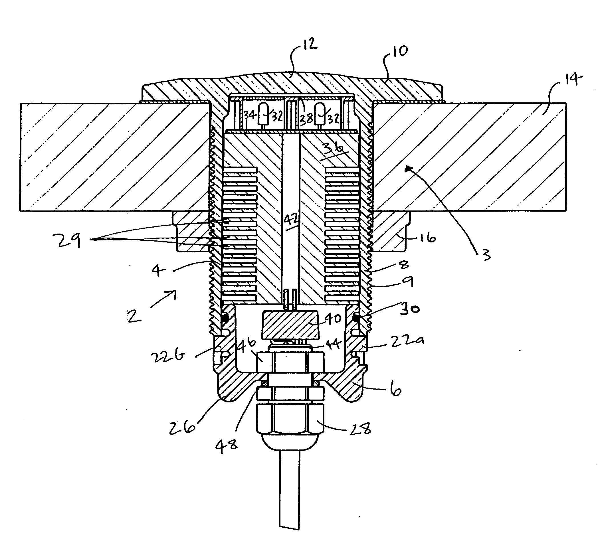
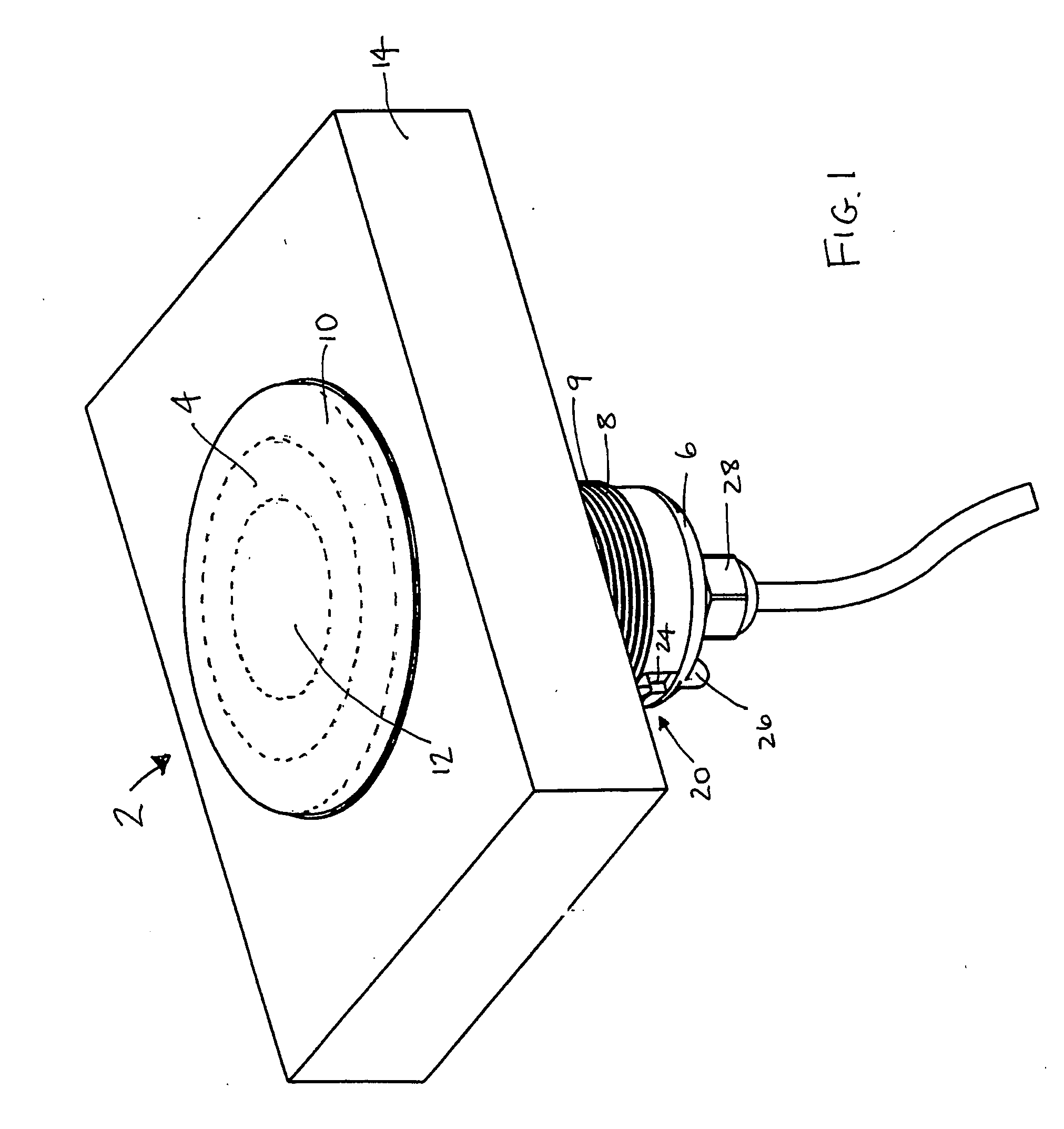
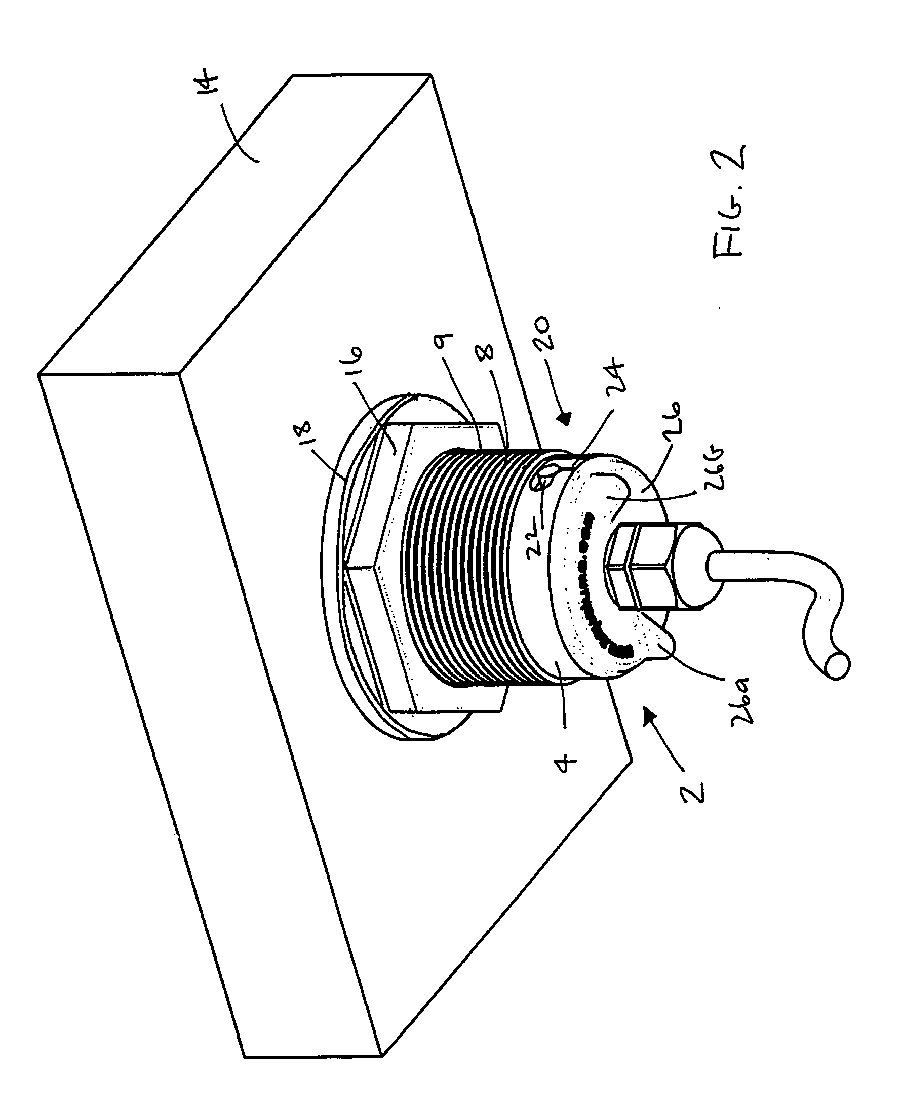
[0038]According to a first embodiment of the present invention, there is provided a lighting apparatus 2 as shown in FIGS. 1 and 2. The lighting apparatus 2 includes a thermoplastic housing 4 having a flanged head 10, and a cylindrical barrel 8 extending from the flanged head 10. The flanged head 10 defines a translucent window 12 and, in use, a light emitting diode (LED) assembly 3 is located within the thermoplastic housing 4 so as to emit light through the translucent window. The lighting apparatus 2 includes a sealing cap 6 for sealing the LED assembly 3 within the thermoplastic housing to thereby isolate the LED assembly 3 from an external environment, such as water, in use. Both the housing and the sealing cap are injection molded from the thermoplastic material. The thermoplastic material is polycarbonate in this example of the invention. As is known, polycarbonate is resistant to corrosion and electricity conduction. A detailed description of the lighting apparatus 2 is prov...


PUM


Abstract

A lighting apparatus (2) includes a housing (4) of plastic material, the housing (4) defining a translucent window (12), and a light emitting diode assembly (3) on a printed circuit board (34). The apparatus (2) may be attached to the hull (14) of a boat by means of a flange (10) and a nut (16). The apparatus (2) may include a heat sink (36) machined from a solid aluminium bar. The housing (4) may be connected to a sealing cap (6). The housing (4) is preferably injection-moulded from a thermoplastic material such as polycarbonate. Electrical wires may extend through a central bore (42) of the heat sink (36) and the sealing cap (6).

Description

TECHNICAL FIELD[0001]The present invention relates to a lighting apparatus and to a light fitting which forms part of the lighting apparatus. The present invention has particular, although not exclusive application to lighting arrangements to be fitted in exposed environments, such as moist or underwater environments or areas of high traffic, such as walkways.BACKGROUND[0002]Many boats have underwater lights fitted to their hull. The lights are typically located beneath the water level in use and, in the event of a globe failure, must be removed from the water so that the globe can be replaced. Accordingly, globes are often not replaced until the boat is raised from the water, which is a costly and therefore infrequent occurrence.[0003]There exist underwater and other mounted lights having consumable components which can be removed in situ. However, such lights usually have an exposed window sealing arrangement that can be prone to corrosion and leakage.[0004]Furthermore, presently ...

Claims


Application Information

Patent Timeline
Patent Type & Authority Applications(United States)
IPC IPC(8): F21V29/00F21W107/20
CPCB63B45/02B63C11/48F21V15/01F21V29/004F21V29/767F21W2111/023F21W2131/401F21Y2101/02F21S8/02F21W2101/04F21Y2115/10F21W2107/20F21V31/005
Inventor AMOR, GRANT HAROLDAMOR, CARL DENIS
Owner AMOR GRANT HAROLD
Why Eureka
Try Eureka